
Solar Logic Circuits Guide
More actions
Disclaimer
Due to the frequency of game updates, all solutions are subject to change and may or may not be functional.
The designs on this page are valid as of v0.2.5906.26015 (2025-09-16)
Guides in this section calls out the sensor and Solar Panel being placed in a specific orientation, but not all guides use the same orientation. When follow a a guide please be sure to place your sensor and solar panel as described in the guide.
Types of Tracking
There are two components to solar tracking, Horizontal position and Vertical position. A solar panel can be positioned using only one of these factors (single axis tracking) or both of these factors (dual axis tracking). Depending on the geometry of sun's sky tack on a particular planet single axis tracking can be very efficient. The solar inclination on The Moon is 0° so single axis solar tracking can be 100% efficient.
Geometry Of Solar Panels and Daylight Sensors
The Horizontal and Vertcal angle measured by the daylight sensor is different from the Solar panels coordinates system. In order to point the solar panel correctly either the angle read from the daylight sensor will need to be recalculated using a Math Unit, or the daylight sensor and solar panel will need to have a different orientation. The Vertical angle measured by the daylight sensor is also different from the Solar panels coordinates system.
If the daylight sensor is positioned horizontally the solar panel's data port should be 90° clockwise from the daylight sensor's Data Port. This will give a Horizontal angles without needing to additional Logic and math. Obtaining a Vertical angle will require additional Logic and Math.
-
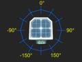 Geometry of values measured by daylight sensor in horizontal (yaw) mode
 -
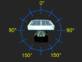 Geometry of values measured by daylight sensor in vertical (pitch) mode
 -
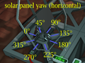 Effect of setting horizontal rotation of a solar panel


Solar tracking using Logic Chips
Two-chip Vertical tracking (Moon only)
Because the sun passes directly East to West with zero solar offset on the moon, it can be tracked using only 2 logic chips.
What do you need:
Place the Solar panel with the data port facing sunrise. Place the Daylight Sensor vertically on the wall with the data port facing down and the sensor facing sunrise. Build a Logic reader and a Batch Writer from the 2 Logic I/O Kits. Set the Logic Reader to read the Vertical Angle from the Daylight Sensor. Set the Batch Writer to Read the Reader and output the Vertical Angle to the Solar Panel (Dual). Rotate the Solar Panel to 270°. Add an Area Power Controller to make sure the Logic Chips do not lose power.
Two-chip Horizontal tracking
With the daylight sensor and solar panel correctly positioned, the solar panel can tack the sun's horizontal track using only 2 chips. On Mars this can yield approximately 80% efficient solar tracking if the solar panel is manually positioned at 45° vertical. Two-chip Horizontal and two-chip Vertical tracking cannot be combined.
What do you need:
Place the Solar panel with the data port facing sunrise. Place the Daylight Sensor horizontally with the data port facing North and the sensor facing up. Build a Logic reader and a Batch Writer from the 2 Logic I/O Kits. Set the Logic reader to read the Horizontal Angle from the Daylight Sensor. Set the Batch Writer to Read the Reader and output the Horizontal Angle to the Solar Panel (Dual). Manually lower the Solar Panel to 45°. Add an Area Power Controller to make sure the Logic Chips do not lose power.
Four Chip Vertical tracking
Vertical tracking requires two additional chips, a Logic Memory and a Math Unit. There are two different method of obtaining the correct vertical solar angle. Either (90-Solar angle) or (Solar angle+90).
What do you need:
- Solar Panel (Dual)
- Kit (Logic I/O) x2
- Kit (Logic Processor)
- Kit (Logic Memory)
- Kit (Sensor) > Daylight Sensor
- Cable
- Area Power Controller X1
Place the Solar panel with the data port facing sunrise. Place the Daylight Sensor horizontally with the data port facing North and the sensor facing up. Build a Logic Reader and a Batch Writer from the 2 Logic I/O Kits. Build a Math Unit from the Logic Processor kit and place the Logic Memory. Set the Logic Reader to read the Vertical Angle from the Daylight Sensor. Set the Logic Memory to 90. Set the left input of the Math Unit to read the Logic Memory. Set the right input of the Math Unit to read the Logic Reader. Set the bottom output of the Math Unit to subtract. Set the Batch Writer to read the Math unit and output the Vertical Angle to the Solar Panel (Dual). Rotate the Solar Panel to 270°. Add an Area Power Controller to make sure the Logic Chips do not lose power.
Combined Solar Tracking
Two-Chip Horizontal Tracking can be upgraded by combining it with Four-Chip Vertical Tracking. Rather than building both at once it is possible to build the Two-Chip Horizontal Tracking and integrate Four-Chip Vertical Tracking at a later time. This is convenient for Brutal Starts as it costs fewer resources and takes less time to get a functioning solar power setup.
What do you need:
- Build the Two-Chip Horizontal Tracking as shown above.
- Build the Four-Chip Vertical Tracking as shown above.
- The daylight sensor and area power controller can be shared between the two setups.
Six-chip dual-axis tracking
To get a "100%" accurate solar tracker on planets with an offset solar arc, you need to include the Horizontal component to the solar angle.
What do you need:
Place the Daylight Sensor facing up, with the Data Port facing north (0 degrees).
| Horizontal | ||||
|---|---|---|---|---|
| Chip | Chip label | IN | VAR | OUT |
| Logic Reader | Horizontal Reader | Daylight Sensor | Horizontal | |
| Batch Writer | Horizontal Writer | Horizontal Reader | Horizontal | Solar Panel |
| Vertical | ||||
| Chip | Chip label | IN | VAR | OUT |
| Logic Reader | Vertical Reader | Daylight Sensor | Vertical | |
| Batch Writer | Vertical Writer | Vertical Correction Math | Vertical | Solar Panel |
| Chip | Chip label | Value | ||
| Logic Memory | Vertical Correction Memory | 90 | ||
| Chip | Chip label | IN 1 | IN 2 | OUT |
| Logic Math | Vertical Correction Math | Vertical Reader | Vertical Correction Memory | Add |
![]()
The panels should align themselves to the sun, you make sure to put the Power Port on the panels facing east (east - 90 degrees). If you've already built the panels and logic with the Power Port facing west, swapping the direction of the sensor so that its Data Port faces south will allow the setup to work with no additional changes.
Solar tracking using Integrated Circuits
Using Intergrated Logic Chips to track the sun will result in a much smaller logic set up, but the implementation might be a bit daunting at first. Conceptually the logic involved is the same.
- The orientation of the Solar Panel and Daylight Senor are the same.
- The Horizontal angle will need to be read from the Daylight Sensor
- The Vertical angle will need to be read for the Daylight Sensor
- The Vertical angle will need to be corrected.
- The following correction must be applied. (Vertical Angel + 90 = Vertical Angle{corrected}
- The Horizontal Angle will need to be sent to the Solar Panel
- The Vertical Angle will need to be sent to the Solar Panel
- Begin the process again
What you need:
And if you don't already have one set up:
Place the Daylight Sensor facing up, note which direction the Data Port is facing, and which direction the solar panel Power Port is facing. These two directions are needed in the code. The Daylight Sensor is connected to the d0 screw, that's all you need.
A simple code example can be found here: https://stationeering.com/tools/ic/_2FpmwojGnBq
This code is considered "inefficient" since it's hard-coded to spam all types of solar panels, even if you don't have them.
A better code example can be found here: https://stationeering.com/tools/ic/_2FpoBEcd3QK
It targets the solar-panel types on d2 and (optionally) d3, so it's less spammy. It also has an option for a display (Kit (Console)) on d1 that shows the sum of power output from both types of panels
duality of orientation
Due to the coordinate system used by solar panels, it is actually possible to capture peak sunlight using two different (but related) H,V coordinates.

This screenshot shows two sets of solar panels, each with its own daylight sensor. Each sensor is oriented differently to properly match its panel and formulas. The panel on the right uses panel.horizontal = daysensor.horizontal; panel.vertical = 90-daysensor.vertical; while the panel on the left uses panel.horizontal = daysensor.horizontal; panel.vertical = daysensor.vertical + 90. They both achieve the same orientation.