
Solar Logic Circuits Guide
More actions
<languages />
Disclaimer
Due to the frequency of game updates, all solutions are subject to change and may or may not be functional.
The designs on this page are valid as of v0.2.5906.26015 (2025-09-25)
Geometry Of Solar Panels and Daylight Sensors
-
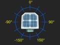 Geometry of values measured by daylight sensor in horizontal (yaw) mode
 -
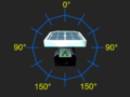 Geometry of values measured by daylight sensor in vertical (pitch) mode
 -
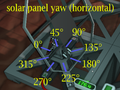 Effect of setting horizontal rotation of a solar panel
 -
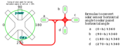 Equations relating horizontal sensor measurements from various orientations to solar panel horizontal rotation


Solar tracking using Logic Chips - Moon
Solar tracking on the Moon is very minimal and straightforward due to its having a near 0° solar angle. You will need the following:
- x1 Daylight Sensor
- x1 Logic Reader
- x1 Batch Writer
- Cable Coils, a Wrench, a Screwdriver, and Wire Cutters at a minimum
The orientation of the Daylight Sensor is important for any solar logic control circuit. Since we are only controlling the vertical alignment (0° solar angle negates the need for horizontal control), the direction of the data port does not matter; however, the blue solar face of the Daylight Sensor must face either east or west. You will have to manually adjust the angle of the horizontal angle on the Solar Panel with a Wrench, dependent on the orientation you build the Solar Panel, and whether the Daylight Sensor faces east or west. Simply wait for the sun to be up and adjust until the panel is ~98% efficient.
Hook up the logical components as follows:
| Component | Port A | Connection A | Port B | Connection B | Port C | Connection C |
|---|---|---|---|---|---|---|
| Logic Reader | IN | Daylight Sensor | VAR | Vertical | N/A | N/A |
| Batch Writer | IN | Logic Reader | OUT VAR | Vertical | OUT TYPE | Solar Panel |
Solar tracking using Logic Chips - Non-Moon
THE FOLLOWING IS A WIP AS OF 1524 CST 25SEP25, IN ACTIVE TESTING MAY BE INACCURATE
Solar tracking not on the Moon remains straightforward, however is inherently more complicated due to not having a near 0° solar angle. You will need the following:
- x1 Daylight Sensor
- x2 Logic Reader
- x2 Batch Writer
- Cable Coils, a Wrench, a Screwdriver, and Wire Cutters at a minimum
- A Labeller is reccommended to differential horizontal/vertical components, but not required
The orientation of the Daylight Sensor is important for any solar logic control circuit. Since we are controlling both the vertical and horizontal alignments, the direction of the data port does matter, and must face either north or south. Additionally, the blue solar face of the Daylight Sensor must face either east or west. The pairing of the facings is as follows:
| Blue Face | Data Port | |
|---|---|---|
| Option 1 | West | South |
| Option 2 | East | North |
Hook up the logical components as follows:
| Component | Port A | Connection A | Port B | Connection B | Port C | Connection C |
|---|---|---|---|---|---|---|
| Vertical Logic Reader | IN | Daylight Sensor | VAR | Vertical | N/A | N/A |
| Vertical Batch Writer | IN | Vertical Logic Reader | OUT VAR | Vertical | OUT TYPE | Solar Panel |
| Horizontal Logic Reader | IN | Daylight Sensor | VAR | Vertical | N/A | N/A |
| Horizontal Batch Writer | IN | Horizontal Logic Reader | OUT VAR | Vertical | OUT TYPE | Solar Panel |