Difference between revisions of "Solar Logic Circuits Guide"
From Unofficial Stationeers Wiki
m (→Notes) |
(Moved ecliptic tracking to the top, as it's become the most popular. Also added a warning to the "Accurate" and "Simple" solar logic setups.) |
||
| Line 7: | Line 7: | ||
Due to the frequency of game updates, all solutions are subject to change and may or may not be functional. | Due to the frequency of game updates, all solutions are subject to change and may or may not be functional. | ||
| − | ---- | + | == Ecliptic Solar Tracking == |
| + | '''Author:''' Eearslya, Neouni, 𝕽𝖘𝖆𝟗𝟕 and everyone of the #logic-circuit-discussion<br> | ||
| + | '''Stationeers Version:''' 0.1.1510.7155 and up<br> | ||
| + | '''Number of Components:''' 10 | ||
| + | |||
| + | === Design === | ||
| + | * 2 [[Sensors|Kit (Sensors)]] | ||
| + | * 4 [[Kit (Logic I/O)]] | ||
| + | * 2 [[Kit (Logic Memory)]] | ||
| + | * 2 [[Kit (Logic Processor)]] ("Math Unit") | ||
| + | |||
| + | This setup takes advantage of the new Horizontal Mode of the [[Kit (Sensor)|Daylight Sensor]], and as such, is a very compact setup. It provides 99% efficiency during the day, only dropping below when the sun is beyond the solar panel's vertical range (less than 15 degrees above the horizon). | ||
| + | |||
| + | To set the second sensor into Horizontal mode, you will need to use a [[Kit (Logic I/O)|Logic Writer]] and a [[Kit (Logic Memory)|Logic Memory]]. Set the Memory to 1, and set the Writer to write to the Daylight Sensor's Mode variable. Once the mode is written to the sensor, you can deconstruct and re-use the I/O and Memory units. They do not need to be left in place to keep the mode set. | ||
| + | |||
| + | [[File:Tilted Solar Tracking.png|full|Diagram]] | ||
| + | |||
| + | === Notes === | ||
| + | * Sensor 1: MUST be facing upwards, Mode 0 (Default) | ||
| + | * Sensor 2: MUST be facing up-side-down, rotated so the power input is facing north, Mode 1 (Horizontal) | ||
| + | * '''Don't forget to write the mode to Sensor 2''' ''once written it will remember it'' | ||
| + | |||
| + | ==== Rotations ==== | ||
| + | We use specific rotations for the daylight sensor and solar panels in this setup to save a Logic Math and a Logic Memory. Refer to this table below to see how your daylight sensor and panels should be rotated. (Note: Sunrise is in the East.) | ||
| + | {| class="wikitable" | ||
| + | ! If the solar panel's power connector points: !! West !! North !! East !! South | ||
| + | |- | ||
| + | | Then rotate Sensor 2's power input: || North || East || South || West | ||
| + | |} | ||
| + | <small>Credit for alternatives: PoolSharkFOG</small> | ||
== Accurate Solar Setup == | == Accurate Solar Setup == | ||
| Line 14: | Line 43: | ||
'''Number of Components:''' 10-12 | '''Number of Components:''' 10-12 | ||
<br>'''Math Formula:''' <code>f(x) = min((x-min(x,15))/1.5, 100)</code> where '''x''' is the solar angle. | <br>'''Math Formula:''' <code>f(x) = min((x-min(x,15))/1.5, 100)</code> where '''x''' is the solar angle. | ||
| + | |||
| + | '''Note: With the introduction of ecliptic solar angles, this setup no longer works at peak efficiency on worlds such as Mars and Europa which have the sun at an angle. This setup will still work on the Moon and in Space.''' | ||
This setup is accurate, giving 495-500W throughout the day, with lower output only when the sun is lower than the panels can physically aim at. | This setup is accurate, giving 495-500W throughout the day, with lower output only when the sun is lower than the panels can physically aim at. | ||
| Line 87: | Line 118: | ||
'''Properties:''' Simple, Inaccurate (Average error: 7.5°)<br> | '''Properties:''' Simple, Inaccurate (Average error: 7.5°)<br> | ||
'''Number of Components:''' 5 | '''Number of Components:''' 5 | ||
| + | |||
| + | '''Note: With the introduction of ecliptic solar angles, this setup no longer works at peak efficiency on worlds such as Mars and Europa which have the sun at an angle. This setup will still work on the Moon and in Space.''' | ||
This imperfect setup is a common starting point. It starts off at 375w of power in the morning, builds up to 500w at zenith (noon) then back to 375. This is due to the fact that solars rotate through only 150 degrees of elevation and that this setup's math is correct only if they rotated through all 180 degrees of solar angle. | This imperfect setup is a common starting point. It starts off at 375w of power in the morning, builds up to 500w at zenith (noon) then back to 375. This is due to the fact that solars rotate through only 150 degrees of elevation and that this setup's math is correct only if they rotated through all 180 degrees of solar angle. | ||
| Line 107: | Line 140: | ||
* Importantly, the solar input power doesn't directly connect to any of the logic writers. This not only ensures your system doesn't lose power but also prevents short-circuiting that would burn cables. | * Importantly, the solar input power doesn't directly connect to any of the logic writers. This not only ensures your system doesn't lose power but also prevents short-circuiting that would burn cables. | ||
* Using 1.7 instead of 1.8 reduces the average error of this design to 6.5° and increases overall power generation, particularly in the afternoon. | * Using 1.7 instead of 1.8 reduces the average error of this design to 6.5° and increases overall power generation, particularly in the afternoon. | ||
| − | |||
| − | |||
| − | |||
| − | |||
| − | |||
| − | |||
| − | |||
| − | |||
| − | |||
| − | |||
| − | |||
| − | |||
| − | |||
| − | |||
| − | |||
| − | |||
| − | |||
| − | |||
| − | |||
| − | |||
| − | |||
| − | |||
| − | |||
| − | |||
| − | |||
| − | |||
| − | |||
| − | |||
| − | |||
| − | |||
| − | |||
| − | |||
| − | |||
</translate> | </translate> | ||
Revision as of 23:19, 28 July 2018
Contents
Disclaimer
Due to the frequency of game updates, all solutions are subject to change and may or may not be functional.
Ecliptic Solar Tracking
Author: Eearslya, Neouni, 𝕽𝖘𝖆𝟗𝟕 and everyone of the #logic-circuit-discussion
Stationeers Version: 0.1.1510.7155 and up
Number of Components: 10
Design
- 2 Kit (Sensors)
- 4 Kit (Logic I/O)
- 2 Kit (Logic Memory)
- 2 Kit (Logic Processor) ("Math Unit")
This setup takes advantage of the new Horizontal Mode of the Daylight Sensor, and as such, is a very compact setup. It provides 99% efficiency during the day, only dropping below when the sun is beyond the solar panel's vertical range (less than 15 degrees above the horizon).
To set the second sensor into Horizontal mode, you will need to use a Logic Writer and a Logic Memory. Set the Memory to 1, and set the Writer to write to the Daylight Sensor's Mode variable. Once the mode is written to the sensor, you can deconstruct and re-use the I/O and Memory units. They do not need to be left in place to keep the mode set.
Notes
- Sensor 1: MUST be facing upwards, Mode 0 (Default)
- Sensor 2: MUST be facing up-side-down, rotated so the power input is facing north, Mode 1 (Horizontal)
- Don't forget to write the mode to Sensor 2 once written it will remember it
Rotations
We use specific rotations for the daylight sensor and solar panels in this setup to save a Logic Math and a Logic Memory. Refer to this table below to see how your daylight sensor and panels should be rotated. (Note: Sunrise is in the East.)
| If the solar panel's power connector points: | West | North | East | South |
|---|---|---|---|---|
| Then rotate Sensor 2's power input: | North | East | South | West |
Credit for alternatives: PoolSharkFOG
Accurate Solar Setup
Authors: Wooodiii, Corvus_bkgk, Enfantcool, Baksch
Properties: Accurate (average error 1.3°), Auto-reset (variant), Power conserving (variant)
Number of Components: 10-12
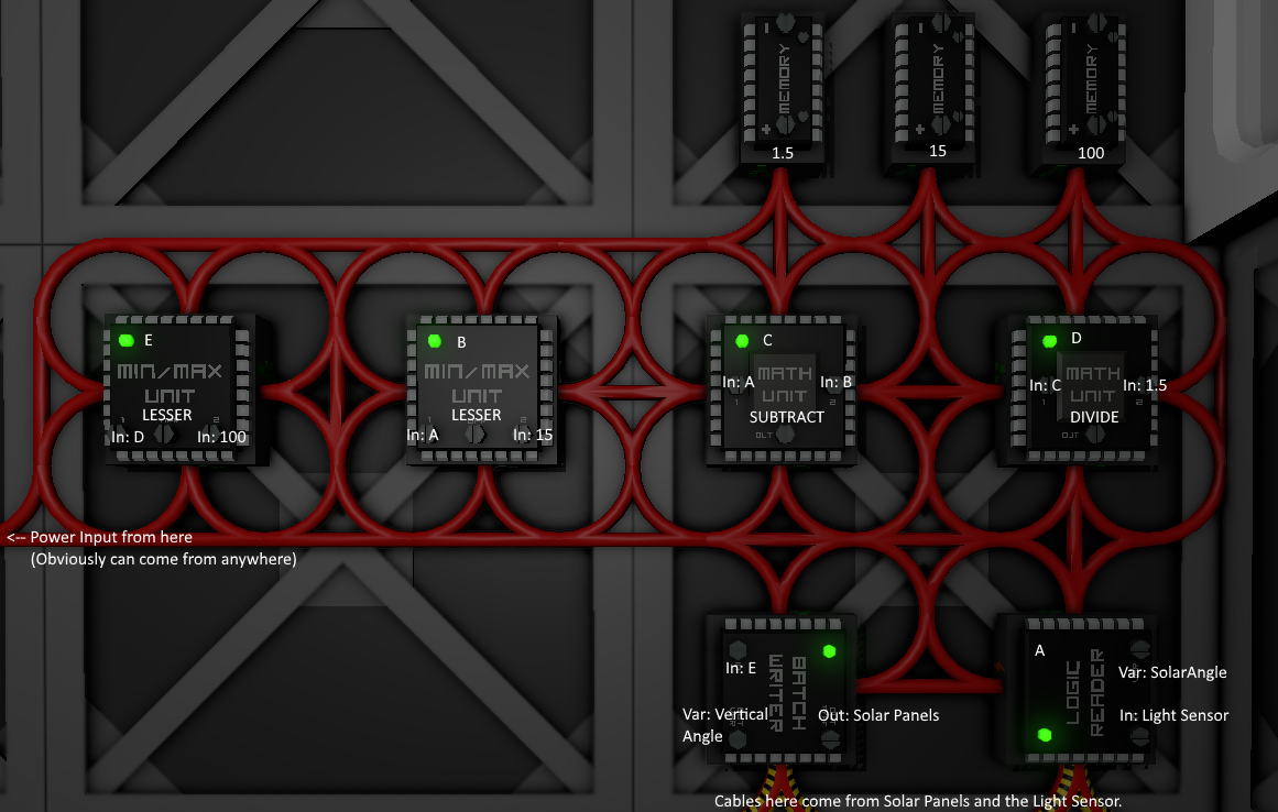
Math Formula: f(x) = min((x-min(x,15))/1.5, 100) where x is the solar angle.
Note: With the introduction of ecliptic solar angles, this setup no longer works at peak efficiency on worlds such as Mars and Europa which have the sun at an angle. This setup will still work on the Moon and in Space.
This setup is accurate, giving 495-500W throughout the day, with lower output only when the sun is lower than the panels can physically aim at.
This setup adjusts for the fact that solar panels rotate through only 150 degrees. Instead of converting using 180/100, this setup converts by doing 150/100. It then clips the value at the edges, where the prior calculation would give elevations that are negative or greater than 100 (representing the fact that we would prefer the panel to track past 0 or 100, aiming all the way down to the horizon instead of stopping 15° short). The listed average error is nonzero only because of this completely unavoidable portion; the error is 0 throughout the 15°-165° portion of the day.
This setup produces the equivalent of 274W averaged over a whole day/night cycle.
Design
- 1 Kit (Sensors) ("Daylight Sensor")
- 2 Kit (Logic I/O) (1 "Logic Reader", 1 "Batch Writer")
- 3 Kit (Logic Memory)
- 4 Kit (Logic Processor) (2 "Math Unit", 2 "Min/Max Unit")
- The Daylight Sensor should face the sunrise.
- Solar panels should be rotated such that 0% vertical faces the sunrise.
| Component (Name) | Settings | Explanation |
|---|---|---|
| Logic Reader (A) | Daylight sensor, Solar angle | Sun's angle above the horizon |
| Memory (15) | 15 | True angle of solar panels at 0 elevation |
| Memory (1.5) | 1.5 | 150/100, the conversion constant from solar angle (range:15-165, i.e. 150) to panel elevation (range:0-100) |
| Min/Max Unit (B) | min(A,15) | Adjustment amount: 15, unless that would take A-B negative, in which case only enough to reach 0 (low edge case). Equivalent to min(A-B,0) but doesn't require storing 0. |
| Math Unit (C) | A-B | Adjusted solar angle |
| Math Unit (D) | C/1.5 | Conversion from solar angle to panel elevation |
| Memory (100) | 100 | Maximum possible panel elevation |
| Min/Max Unit (E) | min(D,100) | Cap elevation to 100 for solar angles past 165° (high edge case). Equivalent to doing min(A-B,165) before step D, but 100 is easier to set in memory than 165. |
| Batch Writer | E -> Solar panels, Vertical angle | Send elevation to solar panels |
Auto-Reset Variant
For panels that automatically reset their facing upon sunset, use two more components, and adjust the final min/max unit:
| Component (Name) | Settings | Explanation |
|---|---|---|
| Logic Reader (L) | Daylight sensor, Activation | 1 while daytime, 0 while nighttime |
| Math Unit (F) | 100*L | Maximum panel elevation, now 100 during day and 0 at night |
| (from above) Min/Max Unit (E) | min(D,F) | Adjusted panel elevation (high edge adjustment) |
Power-Conserving Variant
To conserve power, it's possible to avoid running the entire circuit at night. A transformer can be controlled to power the main logic network above. In this way, only the two new components need to remain powered at all times.
| Component (Name) | Settings | Explanation |
|---|---|---|
| Logic Reader (L) | Daylight sensor, Activation | As in the auto-reset variant above |
| Logic Writer | L -> Transformer, On | Transformer powers main logic network |
Easy/Compact Solar Setup
Author: Evie
Stationeers Version: 0.1.1068.5451
Properties: Simple, Inaccurate (Average error: 7.5°)
Number of Components: 5
Note: With the introduction of ecliptic solar angles, this setup no longer works at peak efficiency on worlds such as Mars and Europa which have the sun at an angle. This setup will still work on the Moon and in Space.
This imperfect setup is a common starting point. It starts off at 375w of power in the morning, builds up to 500w at zenith (noon) then back to 375. This is due to the fact that solars rotate through only 150 degrees of elevation and that this setup's math is correct only if they rotated through all 180 degrees of solar angle.
This setup produces the equivalent of 239W averaged over a whole day/night cycle.
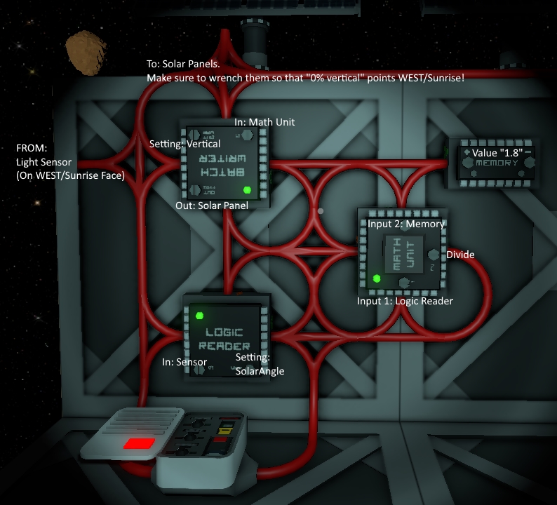
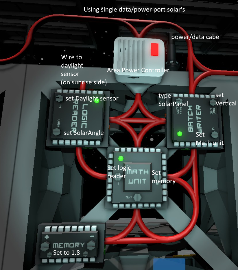
Design
- 1 Kit (Sensors)
- 2 Kit (Logic I/O)
- 1 Kit (Logic Memory)
- 1 Kit (Logic Processor) ("Math Unit")
Notes
- The Daylight Sensor MUST be facing West (sunrise), but its rotation doesn't matter.
- Solar panels should be rotated such as that 0% VERTICAL rotation faces west/sunrise, and 100% VERTICAL faces east/sunset.
- The Area Power Control is necessary for the circuit to stay powered during the night. It also hides all the modules from the rest of your system.
- Importantly, the solar input power doesn't directly connect to any of the logic writers. This not only ensures your system doesn't lose power but also prevents short-circuiting that would burn cables.
- Using 1.7 instead of 1.8 reduces the average error of this design to 6.5° and increases overall power generation, particularly in the afternoon.


