Difference between revisions of "Sensors"
From Unofficial Stationeers Wiki
(→Motion Sensor) |
(Fixed sensor modes behavior) |
||
| Line 31: | Line 31: | ||
}} | }} | ||
| − | The daylight sensor reports whether the sun hits the large grid the sensor is in, as well as the solar angle | + | The daylight sensor reports whether the sun hits the large grid the sensor is in, as well as the solar angle. Looking at the sensor will provide a tool-tip readout of this information, even when not connected to the network. The sensor turns green when sunny. The orientation of the daylight sensor is important, it will read different angle values depending on the orientation. |
| − | The daylight sensor now has a mode property which can be set with logic writer and memory chip, 0 = default | + | The daylight sensor now has a mode property which can be set with logic writer and memory chip, 0 = default, 1 = horizontal, 2 = vertical. Other values will throw an index-out-of-range error in console if you mouse-over the sensor. Each mode defines a specific behavior for how the solar angle is calculated. |
| − | + | == Modes == | |
| + | In default mode, the sensor will return the absolute value of the angle formed by the source of light and the normal vector of the sensor (towards which the grey/green part is facing). 0 means the source of light is facing to the sensor, 90 means it is aligned with the surface the sensor was laid on, and 180 means the source of light is in the back of the sensor. The angle is always a positive value between 0 and 180. | ||
| − | + | In horizontal mode, the sensor will return the angle formed by the reference vector (opposites the network connector) and the projection of the source of light on the surface the sensor was laid on. Positive values designate angles counter-clockwise when facing the sensor. The angle can be negative, ranging between -180 and +180. | |
| − | + | In vertical mode, the sensor behaves exactly like horizontal mode, but the projection occurs on the plane that splits the sensor between the tip and the network connector. The reference vector is the normal vector of the sensor. Positive values designate angles counter-clockwise when looking the sensor from above (opposite of the network connector). Like horizontal mode, the sensor will range between -180 and +180. | |
| − | + | === Notes === | |
| + | |||
| + | Solar panel work using clockwise reference angles, which means depending of the situation you may have to invert the values returned by sensors' horizontal or vertical modes. | ||
The sensor always reports an angle to a logic reader at all times, but the tooltip will not display the angle if the sensor does not have sunlight. | The sensor always reports an angle to a logic reader at all times, but the tooltip will not display the angle if the sensor does not have sunlight. | ||
| Line 47: | Line 50: | ||
See https://stationeers-wiki.com/Solar_Logic_Circuits_Guide for more solar panel logic discussion. | See https://stationeers-wiki.com/Solar_Logic_Circuits_Guide for more solar panel logic discussion. | ||
| − | Examples | + | === Examples === |
| + | On the moon/space : | ||
* If the daylight sensor is fixed on the floor, it will report 90 degrees at sunrise, up to 0 degrees at noon, back to 90 degrees at sunset, to 180 degrees at midnight, and back to 90 at sunrise. | * If the daylight sensor is fixed on the floor, it will report 90 degrees at sunrise, up to 0 degrees at noon, back to 90 degrees at sunset, to 180 degrees at midnight, and back to 90 at sunrise. | ||
* If fixed on a ceiling the cycle will be opposite, i.e.: 90 -> 180 -> 90 -> 0 -> 90. | * If fixed on a ceiling the cycle will be opposite, i.e.: 90 -> 180 -> 90 -> 0 -> 90. | ||
| Line 53: | Line 57: | ||
* If fixed to a west facing wall, the cycle is opposite, i.e.: 180 -> 90 -> 0 -> 90 -> 180. | * If fixed to a west facing wall, the cycle is opposite, i.e.: 180 -> 90 -> 0 -> 90 -> 180. | ||
* If fixed to a north or south facing wall it will stay at 90 degrees all the time. | * If fixed to a north or south facing wall it will stay at 90 degrees all the time. | ||
| + | |||
| + | Other : | ||
| + | * If you lay a sensor on the ground, facing upwards, connector towards south,configured in horizontal mode, it will work like a compass with 0 = north, 90 = east, 180 = south and -90 = west | ||
| + | |||
{{Data Network Header}} | {{Data Network Header}} | ||
| Line 61: | Line 69: | ||
! Parameter Name !! Data Type !! Description | ! Parameter Name !! Data Type !! Description | ||
|- | |- | ||
| − | | Mode || || 0 = Default | + | | Mode || || 0 = Default, 1 = Horizontal, 2 = Vertical |
|- | |- | ||
| Activate || || | | Activate || || | ||
| Line 73: | Line 81: | ||
! Output Name !! Data Type !! Description | ! Output Name !! Data Type !! Description | ||
|- | |- | ||
| − | | Mode || || 0 = Default | + | | Mode || || 0 = Default, 1 = Horizontal, 2 = Vertical |
|- | |- | ||
| Activate || || | | Activate || || | ||
Revision as of 07:07, 21 September 2019
Description
 | |
| Constructing Options | Daylight, Motion or Gas Sensor |
|---|---|
| Properties | |
| Stacks | 5x |
| Recipe | |
| Created With | Electronics Printer, Fabricator, Hydraulic Pipe Bender |
| Cost |
3g Iron, 1g Gold, 1g Copper Hydraulic Pipe Bender has an altered recipe 1g iron instead of 3g |
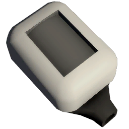
Sensors are used to detect different conditions of the world. They can be read by the Logic Computers as well as used when correctly configured by some devices, such as a Console with a Circuitboard (Airlock Control).
Daylight Sensor
 | |
| Construction | |
|---|---|
| Placed with | Kit (Sensors) |
| Placed on | Small Grid, On Frames |
| Stage 1 | |
| Deconstruction | |
| Deconstructed with | Hand Drill |
| Item received | Kit (Sensors) |
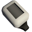
The daylight sensor reports whether the sun hits the large grid the sensor is in, as well as the solar angle. Looking at the sensor will provide a tool-tip readout of this information, even when not connected to the network. The sensor turns green when sunny. The orientation of the daylight sensor is important, it will read different angle values depending on the orientation.
The daylight sensor now has a mode property which can be set with logic writer and memory chip, 0 = default, 1 = horizontal, 2 = vertical. Other values will throw an index-out-of-range error in console if you mouse-over the sensor. Each mode defines a specific behavior for how the solar angle is calculated.
Modes
In default mode, the sensor will return the absolute value of the angle formed by the source of light and the normal vector of the sensor (towards which the grey/green part is facing). 0 means the source of light is facing to the sensor, 90 means it is aligned with the surface the sensor was laid on, and 180 means the source of light is in the back of the sensor. The angle is always a positive value between 0 and 180.
In horizontal mode, the sensor will return the angle formed by the reference vector (opposites the network connector) and the projection of the source of light on the surface the sensor was laid on. Positive values designate angles counter-clockwise when facing the sensor. The angle can be negative, ranging between -180 and +180.
In vertical mode, the sensor behaves exactly like horizontal mode, but the projection occurs on the plane that splits the sensor between the tip and the network connector. The reference vector is the normal vector of the sensor. Positive values designate angles counter-clockwise when looking the sensor from above (opposite of the network connector). Like horizontal mode, the sensor will range between -180 and +180.
Notes
Solar panel work using clockwise reference angles, which means depending of the situation you may have to invert the values returned by sensors' horizontal or vertical modes.
The sensor always reports an angle to a logic reader at all times, but the tooltip will not display the angle if the sensor does not have sunlight.
See https://stationeers-wiki.com/Solar_Logic_Circuits_Guide for more solar panel logic discussion.
Examples
On the moon/space :
- If the daylight sensor is fixed on the floor, it will report 90 degrees at sunrise, up to 0 degrees at noon, back to 90 degrees at sunset, to 180 degrees at midnight, and back to 90 at sunrise.
- If fixed on a ceiling the cycle will be opposite, i.e.: 90 -> 180 -> 90 -> 0 -> 90.
- If fixed to an east facing wall, the cycle from sunrise is: 0 -> 90 -> 180 -> 90 -> 0.
- If fixed to a west facing wall, the cycle is opposite, i.e.: 180 -> 90 -> 0 -> 90 -> 180.
- If fixed to a north or south facing wall it will stay at 90 degrees all the time.
Other :
- If you lay a sensor on the ground, facing upwards, connector towards south,configured in horizontal mode, it will work like a compass with 0 = north, 90 = east, 180 = south and -90 = west
Data Network Properties
These are all Data Network properties of this device.
Data Parameters
These are all parameters that can be written with a Logic Writer, Batch Writer, or Integrated Circuit (IC10).
| Parameter Name | Data Type | Description |
|---|---|---|
| Mode | 0 = Default, 1 = Horizontal, 2 = Vertical | |
| Activate | ||
| On |
Data Outputs
These are all parameters, that can be read with a Logic Reader or a Slot Reader. The outputs are listed in the order a Logic Reader's "VAR" setting cycles through them.
| Output Name | Data Type | Description |
|---|---|---|
| Mode | 0 = Default, 1 = Horizontal, 2 = Vertical | |
| Activate | ||
| SolarAngle | ||
| On |
Motion Sensor
 | |
| Operation | |
|---|---|
| Power Usage | 10W |
| Construction | |
| Placed with | Kit (Sensors) |
| Placed on | Small Grid, On Frames |
| Stage 1 | |
| Deconstruction | |
| Deconstructed with | Hand Drill |
| Item received | Kit (Sensors) |
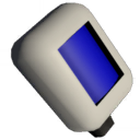
The motion sensor activates when a player or object enters the large grid square where the sensor is, and it will deactivate when no more players or objects are in the area.
Data Network Properties
These are all Data Network properties of this device.
Data Parameters
These are all parameters that can be written with a Logic Writer, Batch Writer, or Integrated Circuit (IC10).
| Parameter Name | Data Type | Description |
|---|
Data Outputs
These are all parameters, that can be read with a Logic Reader or a Slot Reader. The outputs are listed in the order a Logic Reader's "VAR" setting cycles through them.
| Output Name | Data Type | Description |
|---|
Gas Sensor
 | |
| Operation | |
|---|---|
| Power Usage | 10W |
| Construction | |
| Placed with | Kit (Sensors) |
| Placed on | Small Grid, On Frames |
| Stage 1 | |
| Deconstruction | |
| Deconstructed with | Hand Drill |
| Item received | Kit (Sensors) |
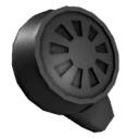
The gas sensor will report information about the gas in the current atmosphere, such as pressure, contents and temperature.
Note: Temperature is given in Kelvin, while your suit gives a readout in Celsius.
Celsius + 273.15 = Kelvin
Data Network Properties
These are all Data Network properties of this device.
Data Parameters
The gas sensor has no Input parameters, it's a read only device.
Data Outputs
These are all parameters, that can be read with a Logic Reader or a Slot Reader. The outputs are listed in the order a Logic Reader's "VAR" setting cycles through them.
| Output Name | Data Type | Description |
|---|---|---|
| Pressure | Float | In kPa |
| Temperature | Float | In Kelvin |
| RatioOxygen | Float | The ratio of oxygen in the atmosphere. A value between 0 (no oxygen at all, or 0%) and 1 ( pure oxygen atmosphere, or 100%) |
| RatioCarbonDioxide | Float | |
| RatioNitrogen | Float | |
| RatioPollutant | Float | |
| RatioVolatiles | Float | |
| RatioWater | Float |
