
Difference between revisions of "Solar Logic Circuits Guide"
From Unofficial Stationeers Wiki
(removed due to community backlash) |
Kittensune (talk | contribs) |
||
| Line 7: | Line 7: | ||
The designs on this page are valid as of v0.2.5906.26015 (2025-09-25) | The designs on this page are valid as of v0.2.5906.26015 (2025-09-25) | ||
| − | ==Solar tracking using Logic Chips == | + | ==Solar tracking using Logic Chips - Moon == |
| − | ''' | + | |
| + | Solar tracking on the [[Worlds|Moon]] is very minimal and straightforward due to its having a near 0° solar angle. You will need the following: | ||
| + | |||
| + | * x1 [[Sensors|Daylight Sensor]] | ||
| + | * x1 [[Logic I/O|Logic Reader]] | ||
| + | * x1 [[Logic I/O|Batch Writer]] | ||
| + | * [[Cables|Cable Coil]]s, a [[Wrench]], a [[Screwdriver]], and [[Wire Cutters]] at a minimum | ||
| + | |||
| + | The orientation of the [[Sensors|Daylight Sensor]] is important for any solar logic control circuit. Since we are only controlling the vertical alignment (0° solar angle negates the need for horizontal control), the direction of the data port does not matter; however, '''the blue solar face of the [[Sensors|Daylight Sensor]] must face either east or west'''. You will have to manually adjust the angle of the horizontal angle on the [[Solar Panel]] with a [[Wrench]], dependent on the orientation you build the [[Solar Panel]], and whether the [[Sensors|Daylight Sensor]] faces east or west. Simply wait for the sun to be up and adjust until the panel is ~98% efficient. | ||
| + | |||
| + | Hook up the logical components as follows: | ||
| + | |||
| + | {| class="wikitable" | ||
| + | |- | ||
| + | ! '''Component''' !! '''Port A''' !! '''Connection A''' !! '''Port B''' !! '''Connection B''' !! '''Port C''' !! '''Connection C''' | ||
| + | |- | ||
| + | | [[Logic I/O|Logic Reader]] || IN || [[Sensors|Daylight Sensor]] || VAR || Vertical || N/A || N/A | ||
| + | |- | ||
| + | | [[Logic I/O|Batch Writer]] || IN || [[Logic I/O|Logic Reader]] || OUT VAR || Vertical || OUT TYPE || [[Solar Panel]] | ||
| + | |} | ||
| + | |||
| + | ==Solar tracking using Logic Chips - Non-Moon == | ||
| + | |||
| + | '''THE FOLLOWING INFORMATION NEEDS TESTING ON A NON-MOON PLANET., I (ERIZAMANU) DON'T HAVE A WORKING NON-MOON SAVE (IM GOING FOR YEAR ACHIEVEMENT ON THE MOON RN) FOLLOWING THE TERRAIN UPDATE, SO IF SOMEONE COULD VERIFY THIS CIRCUIT OFF THE MOON AND DM ME I WOULD BE ETERNALLY GRATEFUL THANKS''' | ||
| + | |||
| + | Solar tracking not on the [[Worlds|Moon]] remains straightforward, however is inherently more complicated due to not having a near 0° solar angle. You will need the following: | ||
| + | |||
| + | * x1 [[Sensors|Daylight Sensor]] | ||
| + | * x2 [[Logic I/O|Logic Reader]] | ||
| + | * x2 [[Logic I/O|Batch Writer]] | ||
| + | * [[Cables|Cable Coil]]s, a [[Wrench]], a [[Screwdriver]], and [[Wire Cutters]] at a minimum | ||
| + | * A [[Labeller]] is recommended to differentiate horizontal/vertical components, but not required | ||
| + | |||
| + | The orientation of the [[Sensors|Daylight Sensor]] is important for any solar logic control circuit. Since we are controlling both the vertical and horizontal alignments, '''the direction of the data port''' does matter, and '''must face either north or south'''. Additionally, '''the blue solar face of the [[Sensors|Daylight Sensor]] must face either east or west''', and the '''[[Solar Panel]] power port must face east or west'''. The pairing of the facings is as follows: | ||
| + | |||
| + | {| class="wikitable" | ||
| + | |- | ||
| + | ! !! '''Blue Face / [[Solar Panel]] Power Port''' !! '''[[Sensors|Daylight Sensor]] Data Port''' | ||
| + | |- | ||
| + | | Option 1 || West || South | ||
| + | |- | ||
| + | | Option 2 || East || North | ||
| + | |} | ||
| + | |||
| + | Hook up the logical components as follows: | ||
| + | |||
| + | {| class="wikitable" | ||
| + | |- | ||
| + | ! '''Component''' !! '''Port A''' !! '''Connection A''' !! '''Port B''' !! '''Connection B''' !! '''Port C''' !! '''Connection C''' | ||
| + | |- | ||
| + | | Vertical [[Logic I/O|Logic Reader]] || IN || [[Sensors|Daylight Sensor]] || VAR || Vertical || N/A || N/A | ||
| + | |- | ||
| + | | Vertical [[Logic I/O|Batch Writer]] || IN || Vertical [[Logic I/O|Logic Reader]] || OUT VAR || Vertical || OUT TYPE || [[Solar Panel]] | ||
| + | |- | ||
| + | | Horizontal [[Logic I/O|Logic Reader]] || IN || [[Sensors|Daylight Sensor]] || VAR || Horizontal || N/A || N/A | ||
| + | |- | ||
| + | | Horizontal [[Logic I/O|Batch Writer]] || IN || Horizontal [[Logic I/O|Logic Reader]] || OUT VAR || Horizontal || OUT TYPE || [[Solar Panel]] | ||
| + | |} | ||
| + | |||
| + | == Solar tracking using IC-10 == | ||
| + | |||
| + | Using the in-game [[IC10]] code is a complicated process that requires learning and/or knowledge of programming in an assembly-level language similar to [https://en.wikipedia.org/wiki/MIPS_architecture MIPS], which IC10 was based upon/inspired by. Even if you are not proficient at programming, given its simplistic nature, a solar tracking script is a great way to start learning [[IC10]], and the general logic and programming skills required to write even more complicated and advanced [[IC10]] code to automate your systems in Stationeers. | ||
| + | |||
| + | If you are unable or prefer not to learn [[IC10]], you can find all sorts of prewritten [[IC10]] code such as [https://steamcommunity.com/sharedfiles/filedetails/?id=1892925984 Tallinu's IC10 Free-form Solar Tracking Script]. | ||
== Geometry Of [[Solar Panel|Solar Panel]]s and [[Sensors|Daylight Sensors]] == | == Geometry Of [[Solar Panel|Solar Panel]]s and [[Sensors|Daylight Sensors]] == | ||
| Line 18: | Line 81: | ||
solar-horiz-formulas.svg|Equations relating horizontal sensor measurements from various orientations to solar panel horizontal rotation | solar-horiz-formulas.svg|Equations relating horizontal sensor measurements from various orientations to solar panel horizontal rotation | ||
</gallery> | </gallery> | ||
| + | |||
| + | == Credits // Additonal Information == | ||
| + | |||
| + | The majority of this content is written by Erizamanu. Feel free to DM me with '''constructive''' suggestions or questions via Discord. | ||
| + | |||
| + | The previous page content was removed following an exchange on the Stationeers Discord between Fuddnir (Previous primary writer) and Risu. The current circuit is an optimized (2 fewer components) version of Fuddnir's circuit that I developed for use in my game. | ||
| + | |||
| + | See the Revision History under Actions for the full change logs. | ||
Revision as of 20:55, 29 September 2025
Contents
Disclaimer
Due to the frequency of game updates, all solutions are subject to change and may or may not be functional.
The designs on this page are valid as of v0.2.5906.26015 (2025-09-25)
Solar tracking using Logic Chips - Moon
Solar tracking on the Moon is very minimal and straightforward due to its having a near 0° solar angle. You will need the following:
- x1 Daylight Sensor
- x1 Logic Reader
- x1 Batch Writer
- Cable Coils, a Wrench, a Screwdriver, and Wire Cutters at a minimum
The orientation of the Daylight Sensor is important for any solar logic control circuit. Since we are only controlling the vertical alignment (0° solar angle negates the need for horizontal control), the direction of the data port does not matter; however, the blue solar face of the Daylight Sensor must face either east or west. You will have to manually adjust the angle of the horizontal angle on the Solar Panel with a Wrench, dependent on the orientation you build the Solar Panel, and whether the Daylight Sensor faces east or west. Simply wait for the sun to be up and adjust until the panel is ~98% efficient.
Hook up the logical components as follows:
| Component | Port A | Connection A | Port B | Connection B | Port C | Connection C |
|---|---|---|---|---|---|---|
| Logic Reader | IN | Daylight Sensor | VAR | Vertical | N/A | N/A |
| Batch Writer | IN | Logic Reader | OUT VAR | Vertical | OUT TYPE | Solar Panel |
Solar tracking using Logic Chips - Non-Moon
THE FOLLOWING INFORMATION NEEDS TESTING ON A NON-MOON PLANET., I (ERIZAMANU) DON'T HAVE A WORKING NON-MOON SAVE (IM GOING FOR YEAR ACHIEVEMENT ON THE MOON RN) FOLLOWING THE TERRAIN UPDATE, SO IF SOMEONE COULD VERIFY THIS CIRCUIT OFF THE MOON AND DM ME I WOULD BE ETERNALLY GRATEFUL THANKS
Solar tracking not on the Moon remains straightforward, however is inherently more complicated due to not having a near 0° solar angle. You will need the following:
- x1 Daylight Sensor
- x2 Logic Reader
- x2 Batch Writer
- Cable Coils, a Wrench, a Screwdriver, and Wire Cutters at a minimum
- A Labeller is recommended to differentiate horizontal/vertical components, but not required
The orientation of the Daylight Sensor is important for any solar logic control circuit. Since we are controlling both the vertical and horizontal alignments, the direction of the data port does matter, and must face either north or south. Additionally, the blue solar face of the Daylight Sensor must face either east or west, and the Solar Panel power port must face east or west. The pairing of the facings is as follows:
| Blue Face / Solar Panel Power Port | Daylight Sensor Data Port | |
|---|---|---|
| Option 1 | West | South |
| Option 2 | East | North |
Hook up the logical components as follows:
| Component | Port A | Connection A | Port B | Connection B | Port C | Connection C |
|---|---|---|---|---|---|---|
| Vertical Logic Reader | IN | Daylight Sensor | VAR | Vertical | N/A | N/A |
| Vertical Batch Writer | IN | Vertical Logic Reader | OUT VAR | Vertical | OUT TYPE | Solar Panel |
| Horizontal Logic Reader | IN | Daylight Sensor | VAR | Horizontal | N/A | N/A |
| Horizontal Batch Writer | IN | Horizontal Logic Reader | OUT VAR | Horizontal | OUT TYPE | Solar Panel |
Solar tracking using IC-10
Using the in-game IC10 code is a complicated process that requires learning and/or knowledge of programming in an assembly-level language similar to MIPS, which IC10 was based upon/inspired by. Even if you are not proficient at programming, given its simplistic nature, a solar tracking script is a great way to start learning IC10, and the general logic and programming skills required to write even more complicated and advanced IC10 code to automate your systems in Stationeers.
If you are unable or prefer not to learn IC10, you can find all sorts of prewritten IC10 code such as Tallinu's IC10 Free-form Solar Tracking Script.
Geometry Of Solar Panels and Daylight Sensors
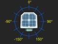
Geometry of horizontal values measured by daylight sensor
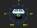
Geometry of vertical values measured by daylight sensor
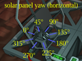
Horizontal rotation of a solar panel
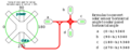
Equations relating horizontal sensor measurements from various orientations to solar panel horizontal rotation


Credits // Additonal Information
The majority of this content is written by Erizamanu. Feel free to DM me with constructive suggestions or questions via Discord.
The previous page content was removed following an exchange on the Stationeers Discord between Fuddnir (Previous primary writer) and Risu. The current circuit is an optimized (2 fewer components) version of Fuddnir's circuit that I developed for use in my game.
See the Revision History under Actions for the full change logs.