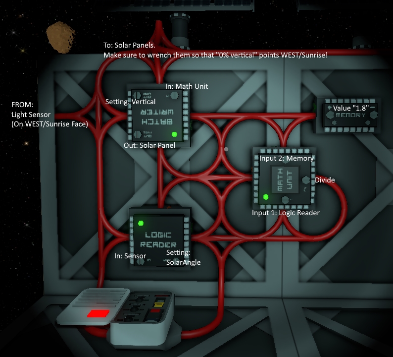
Solar Logic Circuits Guide
From Unofficial Stationeers Wiki
Revision as of 08:29, 19 December 2017 by Evie.codes (talk | contribs) (A guide to controlling your solars... with logic!)
This is a setup created with the help of the http://discord.gg/stationeers discord server. More specifically to figure out the sensor needed to be facing west.
Note that this setup is *lossy*, meaning it's not perfect. It starts off at 375w of power in the morning, builds up to 500w at zenith (noon) then back to 375. This is due purely to the fact that solars aren't perfectly vertical at 0/100 percent. Also, multiplying a 180 degree angle by 0.55 gives you 0 to 99 values, which is also imperfect. However, this is the most COMPACT setup you can achieve without other external tools and with such little hardware.
This setup currently draws 55w base power for one solar, and an additional 5w for each solar you add.
Also note that this is subject to change with each new version of Stationeers, so I can't guarantee it'll even work tomorrow :-/
This setup requires:
- 1 logic I/O (plus one for each of your solars, so minimum 2)
- 2 Memory Chips
- 2 Logic Processors ("Math Unit")
- The Light Sensor MUST be facing West (sunrise), but it's rotation doesn't matter.
- Solar panels should be rotated such as that 0% VERTICAL rotation faces west/sunrise, and 100% VERTICAL faces east/sunset.
- The APC is used for power during the night (yeah it sucks that these things use power tbh), and as you can see the solar input power doesn't directly connect to any of the logic writers. Only the data out from the logic writers goes back into the system. This not only ensures you system doesn't lose power, and doesn't have any loops (which would burn the wires), it also hides all these chips from the rest of your system.

