|
|
| (54 intermediate revisions by 23 users not shown) |
| Line 1: |
Line 1: |
| | [[Category:Tutorials]] | | [[Category:Tutorials]] |
| | <languages /> | | <languages /> |
| − | <translate>
| |
| − |
| |
| | == Disclaimer == | | == Disclaimer == |
| | | | |
| | Due to the frequency of game updates, all solutions are subject to change and may or may not be functional. | | Due to the frequency of game updates, all solutions are subject to change and may or may not be functional. |
| | | | |
| − | == Ecliptic Solar Tracking ==
| + | The designs on this page are valid as of v0.2.3304.16432 (2022-06-06) |
| − | '''Author:''' Eearslya, Neouni, 𝕽𝖘𝖆𝟗𝟕 and everyone of the #logic-circuit-discussion (most recently Enthaply Guy)<br>
| |
| − | '''Stationeers Version:''' 0.1.1510.7155 and up<br>
| |
| − | '''Number of Components:''' 10
| |
| − | | |
| − | === Design ===
| |
| − | * 2 [[Sensors|Kit (Sensors)]]
| |
| − | * 4 [[Kit (Logic I/O)]]
| |
| − | * 3 [[Kit (Logic Memory)]]
| |
| − | * 3 [[Kit (Logic Processor)]] ("Math Unit")
| |
| − | | |
| − | This is a fairly minimalistic 2-axis control setup. You'll need the sensors to be in Mode 1 (horizontal) and Mode 2 (vertical), both facing up. The cable can point in any direction, as the vertical sensor doesn't care and we're already compensating for the horizontal sensor.
| |
| | | | |
| − | To set the sensors, you will need to use a [[Kit (Logic I/O)|Logic Writer]] and a [[Kit (Logic Memory)|Logic Memory]]. Set the memory to 1, and set the writer to write to the first sensor's Mode variable. Then set the Writer to write to the second Sensor, and set the memory to 2 (in that order!). The sensors should say "Mode Horizontal" and "Mode Vertical". Once you have them set, you can deconstruct and re-use the I/O and memory units. They do not need to be left in place to keep the mode set.
| + | While this specific Guide calls out the sensor being place a specific direction(north), its not necessary to orient your sensors to a specific direction. |
| | + | If you find your panels don't point at the sun, you can add either 0,90,180 or 270 to the horizontal until they point at the sun. This guide is an attempt |
| | + | to simplify the setup by removing an extra math, and memory chip(6 chips instead of 8). |
| | | | |
| − | [[File:2-Axis Solar Logic Control.png|full|Screenshot of logic gate control setup for 2-axis tracking for solar panels]]
| + | == Geometry Of Solar Panels and Daylight Sensors == |
| | | | |
| − | === Notes ===
| + | <gallery> |
| − | * Network 1 should have a steady source of power. Ideally, an APC that's fed by the solar panels.
| + | daylight sensor horizontal.png|Geometry of values measured by daylight sensor in horizontal (yaw) mode |
| − | * Network 2 is connected to Logic A and E input, and Logic D and J outputs. It needs to hold solar panel power/data ports and both daylight sensors.
| + | daylight sensor vertical.png|Geometry of values measured by daylight sensor in vertical (pitch) mode |
| | + | solar panel yaw-Horizontal setting.png|Effect of setting horizontal rotation of a solar panel |
| | + | solar-horiz-formulas.svg|Equations relating horizontal sensor measurements from various orientations to solar panel horizontal rotation |
| | + | </gallery> |
| | | | |
| − | * Logic A (reader) reads SolarAngle from daylight sensor in Horizontal mode.
| + | ==Solar tracking using Logic Chips == |
| − | * Logic B (math unit) subtracts Logic A from Logic C. Note that it must be upside down!
| |
| − | * Logic C (memory) should be one of 90, 180, 270 or 360. We're using it to compensate for horizontal sensor orientation. If the sensor cable points the same direction as the solar panels power port, set it to 90. Add 90 for every rotation counterclockwise.
| |
| − | * Logic D (batch writer) reads from Logic B, and writes to Horizontal field for all Solar Panels.
| |
| − | * Logic E (reader) reads SolarAngle from the sensor in Vertical mode.
| |
| − | * Logic F (math unit) divides Logic E by Logic G.
| |
| − | * Logic G (memory) is set to 1.5. It's used to scale from 180° that the sensor reports to the 100% that the solar panels use.
| |
| − | * Logic H (math unit) subtracts Logic F from Logic I. Note that the ''right'' input must be Logic F, and the ''left'' input must be Logic I!
| |
| − | * Logic I (memory) is set to 50. The vertical reader reports 0° at midday and 90° at sunrise/sunset, but we need the panels to be at 50% at midday and 0% at sunrise/sunset.
| |
| − | * Logic J (batch writer) reads from Logic H and writes to Vertical field for all Solar Panels.
| |
| | | | |
| − | <small>Credit for alternatives: PoolSharkFOG</small>
| + | === Six-chip dual-axis tracking === |
| | + | To get a "100%" accurate solar tracker on planets with an offset solar arc, you need to include the Horizontal component to the solar angle. |
| | | | |
| − | This setup can be also programmed in an IC10 chip which saves power because you need only 5 chips instead of 8.
| + | '''What you need:''' |
| − | | + | * Kit (Logic I/O) x4 |
| − | '''Required:'''<br> | + | * Kit (Logic Processor) |
| − | 1 IC10 Chip plus IC housing<br>
| + | * Kit (Logic Memory) |
| − | 2 sensors setup as shown above<br>
| + | * Kit (Sensor) > Daylight Sensor |
| − | 2 memory<br>
| |
| − | 2 Batch Writers that read from memory<br>
| |
| − | <br>
| |
| − | Connect '''Sensor1''' to '''d0''', '''Sensor2''' to '''d1''', '''Memory1''' to '''d2''', '''Memory2''' to '''d3'''.
| |
| − | BatchWriter Horizontal should read from '''Memory1''' and BatchWriter Vertical should read from '''Memory2''' and both ofcourse write to the solar panels.
| |
| − | Use the same setup for the power connector directions as shown above. You do not have to write the mode, this is done in code.
| |
| − | <br><br>
| |
| − | Here is the code for the ic10 chip: [https://stationeering.com/tools/ic#eyJwcm9ncmFtIjoiLy8gU2Vuc29yMSBmYWNlcyB1cCB0byBkMFxuLy8gU2Vuc29yMiBmYWNlcyBkb3duIHRvIGQxXG4vLyB7cG93ZXIgc29sYXIgcGFuZWwsIHBvd2VyIFNlbnNvcjJ9XG4vLyB7V2VzdCwgTm9ydGh9XG4vLyB7Tm9ydGgsIEVhc3R9XG4vLyB7RWFzdCwgU291dGh9XG4vLyB7U291dCwgV2VzdH1cbi8vIENvbm5lY3QgTWVtb3J5MSB0byBkMiBhbmQgTWVtb3J5MiB0byBkM1xuLy8gQmF0Y2ggV3JpdGVycyBtdXN0IHdyaXRlIHRvIFNvbGFyIFBhbmVsOlxuLy8gICAgQmF0Y2hXcml0ZXIxOmluO01lbW9yeTE7dmFyOkhvcml6b250YWxcbi8vICAgIEJhdGNoV3JpdGVyMjppbjtNZW1vcnkyO3ZhcjpWZXJ0aWNhbFxuLy8gZG8gbm90IGluY2x1ZGUgdGhlc2UgY29tbWVudHNcbi8vID09PT09PT09PT09PT09PT09PT09PT09PT09PT1cblxuYWxpYXMgU2Vuc29yMSBkMFxuYWxpYXMgU2Vuc29yMiBkMVxuYWxpYXMgQmF0Y2hIIGQyIFxuYWxpYXMgQmF0Y2hWIGQzXG5cbnNldHVwOlxucyBTZW5zb3IxIE1vZGUgMFxucyBTZW5zb3IyIE1vZGUgMVxuXG5sb29wOlxubCByMCBTZW5zb3IxIFNvbGFyQW5nbGVcbmwgcjEgU2Vuc29yMiBTb2xhckFuZ2xlXG5zdWIgcjAgNzUgcjBcbmRpdiByMCByMCAxLjVcbnMgQmF0Y2hWIFNldHRpbmcgcjBcbnMgQmF0Y2hIIFNldHRpbmcgcjFcbnlpZWxkXG5qIGxvb3BcbiIsInJlZ2lzdGVycyI6eyJpbyI6W3siU29sYXJBbmdsZSI6NTAsIk1vZGUiOjB9LHsiU29sYXJBbmdsZSI6NDUsIk1vZGUiOjF9LHsiU2V0dGluZyI6NDV9LHsiU2V0dGluZyI6MTYuNjY2NjY2NjY2NjY2NjY4fSx7fSx7fSx7fV0sImlvQ29ubmVjdGVkIjpbdHJ1ZSx0cnVlLHRydWUsdHJ1ZSx0cnVlLHRydWUsdHJ1ZV0sImludGVybmFsIjpbMCwwLDAsMCwwLDAsMCwwLDAsMCwwLDAsMCwwLDAsMCwwLDBdfSwicnVuQWZ0ZXJSZWdpc3RlckNoYW5nZSI6ZmFsc2UsInJ1bldpdGhFcnJvcnMiOmZhbHNlfQ== Simulator @ stationeering.com]
| |
| − | | |
| − | == Accurate Solar Setup ==
| |
| − | '''Authors:''' Wooodiii, Corvus_bkgk, Enfantcool, Baksch<br>
| |
| − | '''Properties:''' Accurate (average error 1.3°), Auto-reset (variant), Power conserving (variant)<br>
| |
| − | '''Number of Components:''' 10-12
| |
| − | <br>'''Math Formula:''' <code>f(x) = min((x-min(x,15))/1.5, 100)</code> where '''x''' is the solar angle.
| |
| − | | |
| − | '''Note: With the introduction of ecliptic solar angles, this setup no longer works at peak efficiency on worlds such as Mars and Europa which have the sun at an angle. This setup will still work on the Moon and in Space.'''
| |
| − | | |
| − | This setup is accurate, giving 495-500W throughout the day, with lower output only when the sun is lower than the panels can physically aim at.
| |
| − | | |
| − | This setup adjusts for the fact that solar panels rotate through only 150 degrees. Instead of converting using 180/100, this setup converts by doing 150/100. It then clips the value at the edges, where the prior calculation would give elevations that are negative or greater than 100 (representing the fact that we would prefer the panel to track past 0 or 100, aiming all the way down to the horizon instead of stopping 15° short). The listed average error is nonzero only because of this completely unavoidable portion; the error is 0 throughout the 15°-165° portion of the day.
| |
| − | | |
| − | This setup produces the equivalent of 274W averaged over a whole day/night cycle.
| |
| − | | |
| − | Link to IC Programm : [https://stationeering.com/tools/ic/_14WyiGwVaP1]
| |
| − | | |
| − | === Design ===
| |
| − | * 1 [[Sensors |Kit (Sensors)]] ("Daylight Sensor") | |
| − | * 2 [[Kit (Logic I/O)]] (1 "Logic Reader", 1 "Batch Writer")
| |
| − | * 3 [[Kit (Logic Memory)]] | |
| − | * 4 [[Kit (Logic Processor)]] (2 "Math Unit", 2 "Min/Max Unit") | |
| − | | |
| − | * The [[Sensors#Daylight_Sensor|Daylight Sensor]] should face the sunrise.
| |
| − | * Solar panels should be rotated such that 0% vertical faces the sunrise.
| |
| | | | |
| | + | Place the Daylight Sensor facing up, with the Data Port facing north. |
| | | | |
| | {| class="wikitable" | | {| class="wikitable" |
| | |- | | |- |
| − | ! Component (Name) !! Settings !! Explanation | + | ! '''Horizontal''' |
| | |- | | |- |
| − | | Logic Reader (A) || Daylight sensor, Solar angle || Sun's angle above the horizon
| + | ! '''Chip''' !! '''Chip label''' !! '''IN''' !! '''VAR''' !! '''OUT''' |
| | |- | | |- |
| − | | Memory (15) || 15 || True angle of solar panels at 0 elevation | + | | Logic Reader || Horizontal Reader || Daylight Sensor || Horizontal || |
| | |- | | |- |
| − | | Memory (1.5) || 1.5 || 150/100, the conversion constant from solar angle (range:15-165, i.e. 150) to panel elevation (range:0-100) | + | | Batch Writer || Horizontal Writer || Horizontal Reader || Horizontal || Solar Panel |
| | |- | | |- |
| − | | Min/Max Unit (B) || min(A,15) || Adjustment amount: 15, unless that would take A-B negative, in which case only enough to reach 0 (low edge case). Equivalent to min(A-B,0) but doesn't require storing 0.
| + | ! '''Vertical''' |
| | |- | | |- |
| − | | Math Unit (C) || A-B || Adjusted solar angle
| + | ! '''Chip''' !! '''Chip label''' !! '''IN''' !! '''VAR''' !! '''OUT''' |
| | |- | | |- |
| − | | Math Unit (D) || C/1.5 || Conversion from solar angle to panel elevation | + | | Logic Reader || Vertical Reader || Daylight Sensor || Vertical || |
| | |- | | |- |
| − | | Memory (100) || 100 || Maximum possible panel elevation | + | | Batch Writer || Vertical Writer || Vertical Correction Math || Vertical || Solar Panel |
| | |- | | |- |
| − | | Min/Max Unit (E) || min(D,100) || Cap elevation to 100 for solar angles past 165° (high edge case). Equivalent to doing min(A-B,165) before step D, but 100 is easier to set in memory than 165.
| + | ! '''Chip''' !! '''Chip label''' !! '''Value''' |
| − | |-
| |
| − | | Batch Writer || E -> Solar panels, Vertical angle || Send elevation to solar panels
| |
| − | |}
| |
| − | | |
| − | [[File:Accurate Solar Control.png]]
| |
| − | | |
| − | === Auto-Reset Variant ===
| |
| − | For panels that automatically reset their facing upon sunset, use two more components, and adjust the final min/max unit:
| |
| − | {| class="wikitable"
| |
| − | |-
| |
| − | ! Component (Name) !! Settings !! Explanation | |
| − | |-
| |
| − | | Logic Reader (L) || Daylight sensor, Activation || 1 while daytime, 0 while nighttime
| |
| − | |-
| |
| − | | Math Unit (F) || 100*L || Maximum panel elevation, now 100 during day and 0 at night
| |
| − | |-
| |
| − | | (from above) Min/Max Unit (E) || min(D,'''F''') || Adjusted panel elevation (high edge adjustment)
| |
| − | |}
| |
| − | | |
| − | === Power-Conserving Variant ===
| |
| − | To conserve power, it's possible to avoid running the entire circuit at night. A transformer can be controlled to power the main logic network above. In this way, only the two new components need to remain powered at all times.
| |
| − | | |
| − | {| class="wikitable"
| |
| | |- | | |- |
| − | ! Component (Name) !! Settings !! Explanation
| + | | Logic Memory || Vertical Correction Memory || 90 |
| | |- | | |- |
| − | | Logic Reader (L) || Daylight sensor, Activation || As in the auto-reset variant above
| + | ! '''Chip''' !! '''Chip label''' !! '''IN 1''' !! '''IN 2''' !! '''OUT''' |
| | |- | | |- |
| − | | Logic Writer || L -> Transformer, On || Transformer powers main logic network | + | | Logic Math || Vertical Correction Math || Vertical Reader || Vertical Correction Memory || Add |
| | |} | | |} |
| | | | |
| − | ---- | + | [[File:2022-10-02 Two-axis solar tracking.png|Accurate two-axis solar tracking]] |
| | | | |
| − | == Easy/Compact Solar Setup ==
| + | The panels should align themselves to the sun if you make sure to put the Power Port on the panels facing east (90 degrees). If you've already built the panels and logic with the Power Port facing west, swapping the direction of the sensor so that its Data Port faces south will allow the setup to work with no additional changes. |
| − | '''Author:''' Evie<br>
| |
| − | '''Stationeers Version:''' 0.1.1068.5451<br>
| |
| − | '''Properties:''' Simple, Inaccurate (Average error: 7.5°)<br> | |
| − | '''Number of Components:''' 5
| |
| | | | |
| − | '''Note: With the introduction of ecliptic solar angles, this setup no longer works at peak efficiency on worlds such as Mars and Europa which have the sun at an angle. This setup will still work on the Moon and in Space.'''
| + | == Solar tracking using Integrated Circuits == |
| | + | This is the most powerful way to track the sun, but the implementation might be a bit daunting at first. |
| | | | |
| − | This imperfect setup is a common starting point. It starts off at 375w of power in the morning, builds up to 500w at zenith (noon) then back to 375. This is due to the fact that solars rotate through only 150 degrees of elevation and that this setup's math is correct only if they rotated through all 180 degrees of solar angle.
| + | '''What you need:''' |
| | + | * Integrated Circuit (IC10) |
| | + | * Kit (IC Housing) |
| | + | * Kit (Sensor) > Daylight Sensor |
| | | | |
| − | This setup produces the equivalent of 239W averaged over a whole day/night cycle.
| + | And if you don't already have one set up: |
| | + | * Kit (Computer) |
| | + | * IC Editor Motherboard |
| | | | |
| − | === Design ===
| + | Place the Daylight Sensor facing up, note which direction the Data Port is facing, and which direction the solar panel Power Port is facing. These two directions are needed in the code. The Daylight Sensor is connected to the d0 screw, that's all you need. |
| − | * 1 [[Sensors |Kit (Sensors)]]
| |
| − | * 2 [[Kit (Logic I/O)]]
| |
| − | * 1 [[Kit (Logic Memory)]]
| |
| − | * 1 [[Kit (Logic Processor)]] ("Math Unit")
| |
| | | | |
| − | [[File:Evie's Solar Circuit Setup.jpg|none|Solar Setup Diagram]]
| + | A simple code example can be found here: https://stationeering.com/tools/ic/_2FpmwojGnBq<br> |
| − | [[File:Stationeers-compact solar logic.png|none|A super compact version]]
| + | This code is considered "inefficient" since it's hard-coded to spam all types of solar panels, even if you don't have them. |
| | | | |
| − | === Notes ===
| + | A better code example can be found here: https://stationeering.com/tools/ic/_2FpoBEcd3QK<br> |
| − | * The [[Daylight Sensor]] MUST be facing East (Sunrise), but its rotation doesn't matter.
| + | It targets the solar-panel types on d2 and (optionally) d3, so it's less spammy. It also has an option for a display (Kit (Console)) on d1 that shows the sum of power output from both types of panels |
| − | * Solar panels should be rotated such as that 0% VERTICAL rotation faces East/Sunrise, and 100% VERTICAL faces West/Sunset.
| |
| − | * The [[Area Power Control]] is necessary for the circuit to stay powered during the night. It also hides all the modules from the rest of your system.
| |
| − | * Importantly, the solar input power doesn't directly connect to any of the logic writers. This not only ensures your system doesn't lose power but also prevents short-circuiting that would burn cables.
| |
| − | * Using 1.7 instead of 1.8 reduces the average error of this design to 6.5° and increases overall power generation, particularly in the afternoon.
| |
| − | </translate>
| |
Disclaimer[edit]
Due to the frequency of game updates, all solutions are subject to change and may or may not be functional.
The designs on this page are valid as of v0.2.3304.16432 (2022-06-06)
While this specific Guide calls out the sensor being place a specific direction(north), its not necessary to orient your sensors to a specific direction.
If you find your panels don't point at the sun, you can add either 0,90,180 or 270 to the horizontal until they point at the sun. This guide is an attempt
to simplify the setup by removing an extra math, and memory chip(6 chips instead of 8).
Geometry Of Solar Panels and Daylight Sensors[edit]
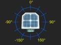
Geometry of values measured by daylight sensor in horizontal (yaw) mode
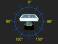
Geometry of values measured by daylight sensor in vertical (pitch) mode
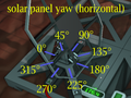
Effect of setting horizontal rotation of a solar panel
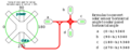
Equations relating horizontal sensor measurements from various orientations to solar panel horizontal rotation
Solar tracking using Logic Chips[edit]
Six-chip dual-axis tracking[edit]
To get a "100%" accurate solar tracker on planets with an offset solar arc, you need to include the Horizontal component to the solar angle.
What you need:
- Kit (Logic I/O) x4
- Kit (Logic Processor)
- Kit (Logic Memory)
- Kit (Sensor) > Daylight Sensor
Place the Daylight Sensor facing up, with the Data Port facing north.
| Horizontal
|
| Chip |
Chip label |
IN |
VAR |
OUT
|
| Logic Reader |
Horizontal Reader |
Daylight Sensor |
Horizontal |
|
| Batch Writer |
Horizontal Writer |
Horizontal Reader |
Horizontal |
Solar Panel
|
| Vertical
|
| Chip |
Chip label |
IN |
VAR |
OUT
|
| Logic Reader |
Vertical Reader |
Daylight Sensor |
Vertical |
|
| Batch Writer |
Vertical Writer |
Vertical Correction Math |
Vertical |
Solar Panel
|
| Chip |
Chip label |
Value
|
| Logic Memory |
Vertical Correction Memory |
90
|
| Chip |
Chip label |
IN 1 |
IN 2 |
OUT
|
| Logic Math |
Vertical Correction Math |
Vertical Reader |
Vertical Correction Memory |
Add
|
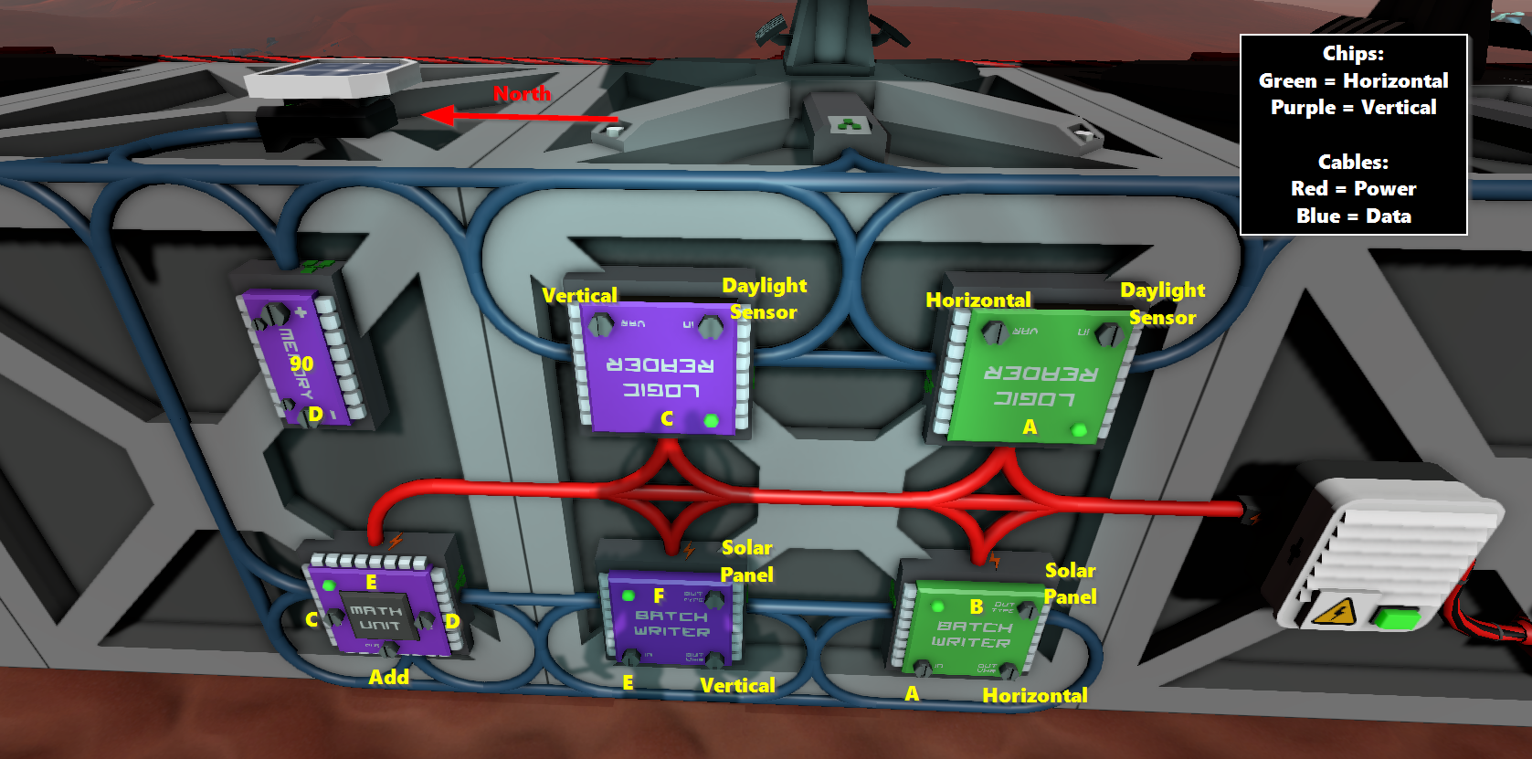
The panels should align themselves to the sun if you make sure to put the Power Port on the panels facing east (90 degrees). If you've already built the panels and logic with the Power Port facing west, swapping the direction of the sensor so that its Data Port faces south will allow the setup to work with no additional changes.
Solar tracking using Integrated Circuits[edit]
This is the most powerful way to track the sun, but the implementation might be a bit daunting at first.
What you need:
- Integrated Circuit (IC10)
- Kit (IC Housing)
- Kit (Sensor) > Daylight Sensor
And if you don't already have one set up:
- Kit (Computer)
- IC Editor Motherboard
Place the Daylight Sensor facing up, note which direction the Data Port is facing, and which direction the solar panel Power Port is facing. These two directions are needed in the code. The Daylight Sensor is connected to the d0 screw, that's all you need.
A simple code example can be found here: https://stationeering.com/tools/ic/_2FpmwojGnBq
This code is considered "inefficient" since it's hard-coded to spam all types of solar panels, even if you don't have them.
A better code example can be found here: https://stationeering.com/tools/ic/_2FpoBEcd3QK
It targets the solar-panel types on d2 and (optionally) d3, so it's less spammy. It also has an option for a display (Kit (Console)) on d1 that shows the sum of power output from both types of panels