
Difference between revisions of "Solar Logic Circuits Guide"
From Unofficial Stationeers Wiki
(Removed the single-axis tracker as the orbital-mechanics have made it obsolete...) |
|||
| (82 intermediate revisions by 31 users not shown) | |||
| Line 1: | Line 1: | ||
[[Category:Tutorials]] | [[Category:Tutorials]] | ||
<languages /> | <languages /> | ||
| − | |||
| − | |||
== Disclaimer == | == Disclaimer == | ||
Due to the frequency of game updates, all solutions are subject to change and may or may not be functional. | Due to the frequency of game updates, all solutions are subject to change and may or may not be functional. | ||
| − | -- | + | The designs on this page are valid as of v0.2.3304.16432 (2022-06-06) |
| − | + | While this specific Guide calls out the sensor being place a specific direction(north), its not necessary to orient your sensors to a specific direction. | |
| − | ' | + | If you find your panels don't point at the sun, you can add either 0,90,180 or 270 to the horizontal until they point at the sun. This guide is an attempt |
| − | + | to simplify the setup by removing an extra math, and memory chip(6 chips instead of 8). | |
| − | |||
| − | |||
| − | + | == Geometry Of Solar Panels and Daylight Sensors == | |
| − | + | <gallery> | |
| + | daylight sensor horizontal.png|Geometry of values measured by daylight sensor in horizontal (yaw) mode | ||
| + | daylight sensor vertical.png|Geometry of values measured by daylight sensor in vertical (pitch) mode | ||
| + | solar panel yaw-Horizontal setting.png|Effect of setting horizontal rotation of a solar panel | ||
| + | solar-horiz-formulas.svg|Equations relating horizontal sensor measurements from various orientations to solar panel horizontal rotation | ||
| + | </gallery> | ||
| − | + | ==Solar tracking using Logic Chips == | |
| − | === | + | === Six-chip dual-axis tracking === |
| − | + | To get a "100%" accurate solar tracker on planets with an offset solar arc, you need to include the Horizontal component to the solar angle. | |
| − | |||
| − | |||
| − | |||
| − | * | + | '''What you need:''' |
| − | + | * Kit (Logic I/O) x4 | |
| + | * Kit (Logic Processor) | ||
| + | * Kit (Logic Memory) | ||
| + | * Kit (Sensor) > Daylight Sensor | ||
| + | |||
| + | Place the Daylight Sensor facing up, with the Data Port facing north. | ||
{| class="wikitable" | {| class="wikitable" | ||
|- | |- | ||
| − | ! | + | ! '''Horizontal''' |
|- | |- | ||
| − | + | ! '''Chip''' !! '''Chip label''' !! '''IN''' !! '''VAR''' !! '''OUT''' | |
|- | |- | ||
| − | | | + | | Logic Reader || Horizontal Reader || Daylight Sensor || Horizontal || |
|- | |- | ||
| − | | | + | | Batch Writer || Horizontal Writer || Horizontal Reader || Horizontal || Solar Panel |
|- | |- | ||
| − | + | ! '''Vertical''' | |
|- | |- | ||
| − | + | ! '''Chip''' !! '''Chip label''' !! '''IN''' !! '''VAR''' !! '''OUT''' | |
|- | |- | ||
| − | | | + | | Logic Reader || Vertical Reader || Daylight Sensor || Vertical || |
|- | |- | ||
| − | | | + | | Batch Writer || Vertical Writer || Vertical Correction Math || Vertical || Solar Panel |
| − | |||
| − | |||
| − | | | ||
| − | |||
| − | | | ||
| − | |||
| − | |||
| − | |||
| − | |||
| − | |||
| − | |||
|- | |- | ||
| − | ! | + | ! '''Chip''' !! '''Chip label''' !! '''Value''' |
|- | |- | ||
| − | | Logic | + | | Logic Memory || Vertical Correction Memory || 90 |
|- | |- | ||
| − | + | ! '''Chip''' !! '''Chip label''' !! '''IN 1''' !! '''IN 2''' !! '''OUT''' | |
|- | |- | ||
| − | | | + | | Logic Math || Vertical Correction Math || Vertical Reader || Vertical Correction Memory || Add |
|} | |} | ||
| − | + | [[File:2022-10-02 Two-axis solar tracking.png|Accurate two-axis solar tracking]] | |
| − | |||
| − | |||
| − | |||
| − | |||
| − | |||
| − | |||
| − | | | ||
| − | |||
| − | |||
| − | |||
| − | |||
| − | |||
| − | |||
| − | |||
| − | |||
| − | |||
| − | |||
| − | |||
| − | |||
| − | |||
| − | |||
| − | |||
| − | |||
| − | |||
| − | |||
| − | |||
| − | |||
| − | |||
| − | + | The panels should align themselves to the sun if you make sure to put the Power Port on the panels facing east (90 degrees). If you've already built the panels and logic with the Power Port facing west, swapping the direction of the sensor so that its Data Port faces south will allow the setup to work with no additional changes. | |
| − | |||
| − | == | + | == Solar tracking using Integrated Circuits == |
| − | + | This is the most powerful way to track the sun, but the implementation might be a bit daunting at first. | |
| − | |||
| − | |||
| − | |||
| − | |||
| + | '''What you need:''' | ||
| + | * Integrated Circuit (IC10) | ||
| + | * Kit (IC Housing) | ||
| + | * Kit (Sensor) > Daylight Sensor | ||
| − | + | And if you don't already have one set up: | |
| − | + | * Kit (Computer) | |
| − | + | * IC Editor Motherboard | |
| − | |||
| − | |||
| − | + | Place the Daylight Sensor facing up, note which direction the Data Port is facing, and which direction the solar panel Power Port is facing. These two directions are needed in the code. The Daylight Sensor is connected to the d0 screw, that's all you need. | |
| − | |||
| − | |||
| − | |||
| − | |||
| − | + | A simple code example can be found here: https://stationeering.com/tools/ic/_2FpmwojGnBq<br> | |
| + | This code is considered "inefficient" since it's hard-coded to spam all types of solar panels, even if you don't have them. | ||
| − | + | A better code example can be found here: https://stationeering.com/tools/ic/_2FpoBEcd3QK<br> | |
| − | + | It targets the solar-panel types on d2 and (optionally) d3, so it's less spammy. It also has an option for a display (Kit (Console)) on d1 that shows the sum of power output from both types of panels | |
| − | |||
| − | |||
| − | |||
| − | |||
Latest revision as of 18:59, 16 March 2024
Contents
Disclaimer[edit]
Due to the frequency of game updates, all solutions are subject to change and may or may not be functional.
The designs on this page are valid as of v0.2.3304.16432 (2022-06-06)
While this specific Guide calls out the sensor being place a specific direction(north), its not necessary to orient your sensors to a specific direction.
If you find your panels don't point at the sun, you can add either 0,90,180 or 270 to the horizontal until they point at the sun. This guide is an attempt
to simplify the setup by removing an extra math, and memory chip(6 chips instead of 8).
Geometry Of Solar Panels and Daylight Sensors[edit]
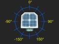
Geometry of values measured by daylight sensor in horizontal (yaw) mode
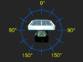
Geometry of values measured by daylight sensor in vertical (pitch) mode
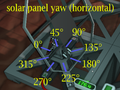
Effect of setting horizontal rotation of a solar panel
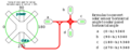
Equations relating horizontal sensor measurements from various orientations to solar panel horizontal rotation


Solar tracking using Logic Chips[edit]
Six-chip dual-axis tracking[edit]
To get a "100%" accurate solar tracker on planets with an offset solar arc, you need to include the Horizontal component to the solar angle.
What you need:
- Kit (Logic I/O) x4
- Kit (Logic Processor)
- Kit (Logic Memory)
- Kit (Sensor) > Daylight Sensor
Place the Daylight Sensor facing up, with the Data Port facing north.
| Horizontal | ||||
|---|---|---|---|---|
| Chip | Chip label | IN | VAR | OUT |
| Logic Reader | Horizontal Reader | Daylight Sensor | Horizontal | |
| Batch Writer | Horizontal Writer | Horizontal Reader | Horizontal | Solar Panel |
| Vertical | ||||
| Chip | Chip label | IN | VAR | OUT |
| Logic Reader | Vertical Reader | Daylight Sensor | Vertical | |
| Batch Writer | Vertical Writer | Vertical Correction Math | Vertical | Solar Panel |
| Chip | Chip label | Value | ||
| Logic Memory | Vertical Correction Memory | 90 | ||
| Chip | Chip label | IN 1 | IN 2 | OUT |
| Logic Math | Vertical Correction Math | Vertical Reader | Vertical Correction Memory | Add |
![]()
The panels should align themselves to the sun if you make sure to put the Power Port on the panels facing east (90 degrees). If you've already built the panels and logic with the Power Port facing west, swapping the direction of the sensor so that its Data Port faces south will allow the setup to work with no additional changes.
Solar tracking using Integrated Circuits[edit]
This is the most powerful way to track the sun, but the implementation might be a bit daunting at first.
What you need:
- Integrated Circuit (IC10)
- Kit (IC Housing)
- Kit (Sensor) > Daylight Sensor
And if you don't already have one set up:
- Kit (Computer)
- IC Editor Motherboard
Place the Daylight Sensor facing up, note which direction the Data Port is facing, and which direction the solar panel Power Port is facing. These two directions are needed in the code. The Daylight Sensor is connected to the d0 screw, that's all you need.
A simple code example can be found here: https://stationeering.com/tools/ic/_2FpmwojGnBq
This code is considered "inefficient" since it's hard-coded to spam all types of solar panels, even if you don't have them.
A better code example can be found here: https://stationeering.com/tools/ic/_2FpoBEcd3QK
It targets the solar-panel types on d2 and (optionally) d3, so it's less spammy. It also has an option for a display (Kit (Console)) on d1 that shows the sum of power output from both types of panels