Difference between revisions of "Power Controller"
From Unofficial Stationeers Wiki
m (duplicate) |
(its) |
||
| (8 intermediate revisions by 7 users not shown) | |||
| Line 1: | Line 1: | ||
| + | [[Category:Power]] | ||
<languages /> | <languages /> | ||
<translate> | <translate> | ||
| Line 4: | Line 5: | ||
| name = Power Controller | | name = Power Controller | ||
| image = [[File:ItemAreaPowerControl.png]] | | image = [[File:ItemAreaPowerControl.png]] | ||
| + | | prefabhash = 1757673317 | ||
| + | | prefabname = ItemAreaPowerControl | ||
| stacks = 5 | | stacks = 5 | ||
| maxinpower = 10W for the APC<br>+ 1000W Battery Charging<br>+ Output Load | | maxinpower = 10W for the APC<br>+ 1000W Battery Charging<br>+ Output Load | ||
| Line 22: | Line 25: | ||
== Usage == <!--T:2--> | == Usage == <!--T:2--> | ||
| − | The APC can be opened with a [[Crowbar]], once opened the switch must be set to the 'ON' state for it to function. A [[Battery Cell]] can be added to act as a power buffer for the subnetwork in the event the main power network gets disconnected | + | The APC can be opened with a [[Crowbar]], once opened the switch must be set to the 'ON' state for it to function. A [[Battery Cell]] can be added to act as a power buffer for the subnetwork in the event the main power network gets disconnected. |
<br><br> | <br><br> | ||
| − | The APC can generally be used for machines with varying power requirements such as the Auto lathe, Electronics Printer, Fabricator, Arc Furnace, and more. This will allow all these machines to take lots of power in short intervals as long as the APC has a battery. | + | The APC can generally be used for machines with varying power requirements such as the Auto lathe, Electronics Printer, Fabricator, Arc Furnace, and more. This will allow all these machines to take lots of power in short intervals as long as the APC has a battery. Unlike the [[Transformer]], the APC will not limit the amount of power it passes through. |
| − | If sufficient power is available upstream, the APC acts as a pass through and will not limit | + | If sufficient power is available upstream, the APC acts as a pass through and will not limit its output power, it is recommended to use a [[Fuse|Cable Fuse]] or [[Transformer|Transformer (Small)]] when powering a non-heavy cable network to prevent overdraw. |
{{Data Network Header}} There is no difference in parameters, whether the logic network is connected to the input or output of the Area Power Control. | {{Data Network Header}} There is no difference in parameters, whether the logic network is connected to the input or output of the Area Power Control. | ||
| Line 36: | Line 39: | ||
! Value !! Display !! Meaning | ! Value !! Display !! Meaning | ||
|- | |- | ||
| − | | 0 || Grey || | + | | 0 || Grey || The Area Power Control is turned off or is missing a battery. |
|- | |- | ||
| 1 || Red || No battery in the Area Power Control and there is power drawn from the output. | | 1 || Red || No battery in the Area Power Control and there is power drawn from the output. | ||
Latest revision as of 15:16, 2 October 2025
 | |
| Max Input Power |
10W for the APC + 1000W Battery Charging + Output Load |
|---|---|
| Max Output Power | No Limit |
| Properties | |
| Stacks | Yes (5) |
| Recipe | |
| Created With | Electronics Printer, Fabricator |
| Cost | 5g Iron, 2g Copper, 3g Solder |
| Logic | |
| Item Hash | 1757673317 |
| Item Name | ItemAreaPowerControl |
| Operation | |
|---|---|
| Power Usage | 10W |
| Construction | |
| Placed with | Power Controller |
| Placed on | Small Grid |
| Stage 1 | |
| Deconstruction | |
| Deconstructed with | Hand Drill |
| Item received | Power Controller |
Contents
Description[edit]
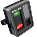
The Area Power Controller is used to segregate power into their own subnetworks and reduce power fluctuations.
Usage[edit]
The APC can be opened with a Crowbar, once opened the switch must be set to the 'ON' state for it to function. A Battery Cell can be added to act as a power buffer for the subnetwork in the event the main power network gets disconnected.
The APC can generally be used for machines with varying power requirements such as the Auto lathe, Electronics Printer, Fabricator, Arc Furnace, and more. This will allow all these machines to take lots of power in short intervals as long as the APC has a battery. Unlike the Transformer, the APC will not limit the amount of power it passes through.
If sufficient power is available upstream, the APC acts as a pass through and will not limit its output power, it is recommended to use a Cable Fuse or Transformer (Small) when powering a non-heavy cable network to prevent overdraw.
Data Network Properties[edit]
These are all Data Network properties of this device. There is no difference in parameters, whether the logic network is connected to the input or output of the Area Power Control.
Mode Values[edit]
This shows the values of the "Mode" property, mapped to what the display will show.
| Value | Display | Meaning |
|---|---|---|
| 0 | Grey | The Area Power Control is turned off or is missing a battery. |
| 1 | Red | No battery in the Area Power Control and there is power drawn from the output. |
| 2 | Blue-red blinking | There is a battery in the Area Power Control, the output draw is greater than the input and the battery is discharging. |
| 3 | Blue-green blinking | There is a battery in the Area Power Control, the output draw is less than the input and the battery is charging. |
| 4 | Green | There is a battery in the Area Power Control, the output draw is less than the input and the battery is fully charged. |
Data Parameters[edit]
These are all parameters that can be written with a Logic Writer, Batch Writer, or Integrated Circuit (IC10).
| Parameter Name | Data Type | Description |
|---|---|---|
| Open | Boolean | Opens the Area Power Control lid, when set to 1. Closes it, when set to 0. |
| Mode | Integer | Sets the mode to the passed value. This will only be set for less than a second, before the Area Power Control will override it with it's current mode. (See Mode Values) |
| Lock | Boolean | Locks the Area Power Control, when set to 1. Unlocks it, when set to 0. |
| On | Boolean | Turns the Area Power Control on, when set to 1. Turns it off, when set to 0. |
Data Outputs[edit]
These are all parameters, that can be read with a Logic Reader or a Slot Reader. The outputs are listed in the order a Logic Reader's "VAR" setting cycles through them.
| Output Name | Data Type | Description |
|---|---|---|
| Power | Boolean | Returns whether the Area Power Control is receiving power and is turned on. (0 for no, 1 for yes) |
| Open | Boolean | Returns whether the Area Power Control is open. (0 for no, 1 for yes) |
| Mode | Integer | Returns the current mode of the Area Power Control. (See Mode Values) |
| Error | Boolean | Returns whether the Area Power Control is flashing an error. (0 for no, 1 for yes) |
| Lock | Boolean | Returns whether the Area Power Control is locked. (0 for no, 1 for yes) |
| Charge | Integer | Returns the currently available power, that can be output, in Watts. (Input power plus the charge of the battery in the Area Power Control.) |
| Maximum | Integer | Returns the maximum charge of the battery in the Area Power Control, in Watts. |
| Ratio | Float | Returns a range from 0.0 to 1.0. It returns the current charge percentage of the battery in the Area Power Control. |
| PowerPotential | Integer | Returns the current amount of power, available to the Area Power Control input, in Watts. |
| PowerActual | Integer | Returns the current amount of power, output by the Area Power Control, in Watts. |
| On | Boolean | Returns whether the Area Power Control is on. (0 for no, 1 for yes) |
| RequiredPower | Integer | Returns the current amount of power needed at the input, in Watts. (This includes the amount of power draw of the battery inside.) |
History[edit]
- In older versions of the game, the APC had specific Input and Output connection sides until a later update added a variant of the APC with reversed sides.
- In older versions of the game, a battery must be placed in the APC for it to function. This is no longer the case after the power rework update in v0.1.1062.5426 as you do not need a battery in the APC for it to function anymore.
