Difference between revisions of "Console"
From Unofficial Stationeers Wiki
ServerToni (talk | contribs) m |
|||
| (23 intermediate revisions by 15 users not shown) | |||
| Line 1: | Line 1: | ||
| − | [[ | + | <languages/> |
| + | <translate> | ||
| + | {{Itembox | ||
| + | | name = Kit (Consoles) | ||
| + | | image = [[File:ItemKitConsole.png]] | ||
| + | | createdwith = [[Electronics Printer]], [[Fabricator]] | ||
| + | | cost = 2g [[Iron]], 5g [[Copper]], 3g [[Gold]] | ||
| + | | stacks = 5 | ||
| + | }} | ||
{{Structurebox | {{Structurebox | ||
| − | | name = Console | + | | name = Console |
| − | | | + | | image = [[File:Console.jpg]] |
| − | | | + | | power_usage = 50W |
| + | | placed_with_item = [[Kit (Consoles)]] | ||
| + | | placed_on_grid = Small Grid, On Frames | ||
| + | | const_with_item1 = [[Circuitboard]] | ||
| + | | decon_with_tool1 = [[Hand Drill]] | ||
| + | | item_rec1 = [[Kit (Consoles)]] | ||
| + | | const_with_item2 = [[Glass Sheets|Glass Sheet]] | ||
| + | | item_rec2 = [[Circuitboard]] | ||
| + | | decon_with_tool3 = [[Crowbar]] | ||
| + | | item_rec3 = [[Glass Sheets|Glass Sheet]] | ||
}} | }} | ||
| − | == | + | = Console = |
| + | == Description == <!--T:1--> | ||
| + | <blockquote><q>This Norsec-designed control box manages devices such as the Active Vent, Passive Vent, Gas Sensor and Composite Door, depending on which circuitboard is inserted into the unit. It has a shared data/power port.</q> | ||
| + | <q>A completed console displays all devices connected to the current power network. Any devices not related to the installed circuitboard will be greyed-out and inoperable. Consoles are locked once a Data Disk is removed.</q><br> | ||
| + | '''- Stationpedia'''</blockquote> | ||
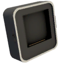
| − | The console can be | + | The console is one device of the Console item kit. The console can be fitted with a [[Circuitboard]]. When putting in a data disk, the console can be configured after being fully constructed with a circuitboard. After putting out the data disk it runs like previously configured. |
| + | There is the Console (Variant 1 of the kit) which has a mixed input (data and energy) and the Console Dual (Variant 2 of the kit) which has two inputs (one for energy and one for data). | ||
| − | == Example set up == | + | == Example set up == <!--T:2--> |
| + | <!--T:3--> | ||
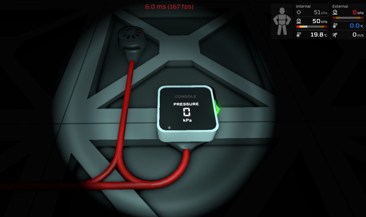
For example one can set it to pressure measurement (requires gas circuit board inside) which allows one to read out the actual pressure value of a connected gas [[sensors|sensor]]. (Setup shown in picture) | For example one can set it to pressure measurement (requires gas circuit board inside) which allows one to read out the actual pressure value of a connected gas [[sensors|sensor]]. (Setup shown in picture) | ||
| − | == Tips == | + | == Tips == <!--T:4--> |
| + | |||
| + | <!--T:5--> | ||
| + | * You need to insert a Circuit Board and then put a sheet of glass over it to complete construction. | ||
| + | * To display general readings, only the Graph Display Circuit Board will find all the devices which are connected to your power grid. Any available readings will be shown on the select list. | ||
| + | * For other specialized Circuit Boards (Gas, Power, etc.) the only values that can be displayed are those related to the function of that board. | ||
| + | |||
| + | == Deconstruction == <!--T:6--> | ||
| + | First remove the glass sheet with a [[Crowbar]]. The device itself is deconstructed with the [[Hand Drill]]. | ||
| + | |||
| + | = Console, Console Dual and Console Monitor = | ||
| + | |||
| + | {{Data Network Header}} | ||
| + | |||
| + | {{Data Parameters}} | ||
| + | {| class="wikitable" | ||
| + | |- | ||
| + | ! Parameter Name !! Data Type !! Description | ||
| + | |- | ||
| + | | Open || Boolean || (Unknown) | ||
| + | |- | ||
| + | | On || Boolean || Turns the Console on, when set to 1. Turns it off, when set to 0. | ||
| + | |} | ||
| + | |||
| + | {{Data Outputs}} | ||
| + | {| class="wikitable" | ||
| + | |- | ||
| + | ! Output Name !! Data Type !! Description | ||
| + | |- | ||
| + | | Power || Boolean || Returns whether the Console is turned on and receives power. (0 for no, 1 for yes) | ||
| + | |- | ||
| + | | Open || Boolean || (Unknown) | ||
| + | |- | ||
| + | | Error || Boolean || Returns whether the Console is flashing an error. (0 for no, 1 for yes) | ||
| + | |- | ||
| + | | On || Boolean || Returns whether the Console is turned on. (0 for no, 1 for yes) | ||
| + | |- | ||
| + | | RequiredPower || Integer || Returns the current amount of power required by the Console, in watts. | ||
| + | |} | ||
| + | |||
| + | = LED Display (Small, Medium and Large) = | ||
| + | {| class="wikitable" | ||
| + | |- | ||
| + | ! Name !! Picturne !! Placed with | ||
| + | |- | ||
| + | | Small display LED || [[File:Small display.png|thumb]] || 1 - Kit (Consoles) | ||
| + | |- | ||
| + | | Medium display LED || [[File:Screenshot 2.png|thumb]] || 2 - Kit (Consoles) | ||
| + | |- | ||
| + | | Large display LED || [[File:Screenshot 3.png|thumb]] || 3 - Kit (Consoles) | ||
| + | |} | ||
| + | |||
| − | + | {{Data Network Header}} | |
| − | |||
| − | |||
| − | == | + | === Mode Values === |
| + | These lists the values and meanings for the "Mode" property of the LED Display. | ||
| + | {| class="wikitable" | ||
| + | |- | ||
| + | ! Value !! Meaning !! "Setting" parameter interpretation | ||
| + | |- | ||
| + | | 0 || Normal number display || Direct display as a number. Values smaller than 1.000E-07 will be displayed as 0. <!-- tested with large led display, might want to see if other sizes are the same --> | ||
| + | |- | ||
| + | | 1 || Percentage number display || Input range of 0.0 to 1.0 is interpolated and displayed as the range 0% to 100% | ||
| + | |- | ||
| + | | 2 || Power display || Adds a watt suffix (W) to the number. Also divides the number as needed and adds a metric unit prefix to the suffix. (e.g. kW) | ||
| + | |} | ||
| − | + | {{Data Parameters}} | |
| + | {| class="wikitable" | ||
| + | |- | ||
| + | ! Parameter Name !! Data Type !! Description | ||
| + | |- | ||
| + | | Mode || Integer || Sets the display mode of the LED Display to the passed value. (See [[#Mode Values|Mode Values]]) | ||
| + | |- | ||
| + | | Setting || Float || Sets the raw number to display on the LED Display. | ||
| + | |- | ||
| + | | On || Boolean || Turns the LED Display on, when set to 1. Turns it off, when set to 0. | ||
| + | |- | ||
| + | | Color || Integer || Sets the color of the text on the LED Display. (See [[Data Network Colors]]) | ||
| + | |} | ||
| − | = | + | {{Data Outputs}} |
| − | + | {| class="wikitable" | |
| + | |- | ||
| + | ! Output Name !! Data Type !! Description | ||
| + | |- | ||
| + | | Power || Boolean || Returns whether the LED Display is turned on and receives power. (0 for no, 1 for yes) | ||
| + | |- | ||
| + | | Mode || Integer || Returns the mode of the LED Display. (See [[#Mode Values|Mode Values]]) | ||
| + | |- | ||
| + | | Error || Boolean || Returns whether the LED Display is flashing an error. (0 for no, 1 for yes) | ||
| + | |- | ||
| + | | Setting || Float || Returns the "Setting" value of the LED Display. | ||
| + | |- | ||
| + | | On || Boolean || Returns whether the LED Display is turned on. (0 for no, 1 for yes) | ||
| + | |- | ||
| + | | RequiredPower || Integer || Returns the current amount of power, required by the LED Display, in watts. | ||
| + | |- | ||
| + | | Color || Integer || Returns the color setting of the LED Display. (See [[Data Network Colors]]) | ||
| + | |} | ||
| + | </translate> | ||
| + | |||
| + | [[Category:Circuitboards]] | ||
| + | [[Category:Data Network]] | ||
| + | [[Category:Machines]] | ||
Latest revision as of 06:37, 18 May 2024
 | |
| Properties | |
|---|---|
| Stacks | Yes (5) |
| Recipe | |
| Created With | Electronics Printer, Fabricator |
| Cost | 2g Iron, 5g Copper, 3g Gold |
 | |
| Operation | |
|---|---|
| Power Usage | 50W |
| Construction | |
| Placed with | Kit (Consoles) |
| Placed on | Small Grid, On Frames |
| Stage 1 | |
| Next Stage Construction | |
| Constructed with item | Circuitboard |
| Deconstruction | |
| Deconstructed with | Hand Drill |
| Item received | Kit (Consoles) |
| Stage 2 | |
| Next Stage Construction | |
| Constructed with item | Glass Sheet |
| Deconstruction | |
| Item received | Circuitboard |
| Stage 3 | |
| Deconstruction | |
| Deconstructed with | Crowbar |
| Item received | Glass Sheet |
Contents
Console[edit]
Description[edit]
This Norsec-designed control box manages devices such as the Active Vent, Passive Vent, Gas Sensor and Composite Door, depending on which circuitboard is inserted into the unit. It has a shared data/power port.- Stationpedia
A completed console displays all devices connected to the current power network. Any devices not related to the installed circuitboard will be greyed-out and inoperable. Consoles are locked once a Data Disk is removed.
The console is one device of the Console item kit. The console can be fitted with a Circuitboard. When putting in a data disk, the console can be configured after being fully constructed with a circuitboard. After putting out the data disk it runs like previously configured. There is the Console (Variant 1 of the kit) which has a mixed input (data and energy) and the Console Dual (Variant 2 of the kit) which has two inputs (one for energy and one for data).
Example set up[edit]
For example one can set it to pressure measurement (requires gas circuit board inside) which allows one to read out the actual pressure value of a connected gas sensor. (Setup shown in picture)
Tips[edit]
- You need to insert a Circuit Board and then put a sheet of glass over it to complete construction.
- To display general readings, only the Graph Display Circuit Board will find all the devices which are connected to your power grid. Any available readings will be shown on the select list.
- For other specialized Circuit Boards (Gas, Power, etc.) the only values that can be displayed are those related to the function of that board.
Deconstruction[edit]
First remove the glass sheet with a Crowbar. The device itself is deconstructed with the Hand Drill.
Console, Console Dual and Console Monitor[edit]
Data Network Properties[edit]
These are all Data Network properties of this device.
Data Parameters[edit]
These are all parameters that can be written with a Logic Writer, Batch Writer, or Integrated Circuit (IC10).
| Parameter Name | Data Type | Description |
|---|---|---|
| Open | Boolean | (Unknown) |
| On | Boolean | Turns the Console on, when set to 1. Turns it off, when set to 0. |
Data Outputs[edit]
These are all parameters, that can be read with a Logic Reader or a Slot Reader. The outputs are listed in the order a Logic Reader's "VAR" setting cycles through them.
| Output Name | Data Type | Description |
|---|---|---|
| Power | Boolean | Returns whether the Console is turned on and receives power. (0 for no, 1 for yes) |
| Open | Boolean | (Unknown) |
| Error | Boolean | Returns whether the Console is flashing an error. (0 for no, 1 for yes) |
| On | Boolean | Returns whether the Console is turned on. (0 for no, 1 for yes) |
| RequiredPower | Integer | Returns the current amount of power required by the Console, in watts. |
LED Display (Small, Medium and Large)[edit]
| Name | Picturne | Placed with |
|---|---|---|
| Small display LED | 1 - Kit (Consoles) | |
| Medium display LED | 2 - Kit (Consoles) | |
| Large display LED | 3 - Kit (Consoles) |
Data Network Properties[edit]
These are all Data Network properties of this device.
Mode Values[edit]
These lists the values and meanings for the "Mode" property of the LED Display.
| Value | Meaning | "Setting" parameter interpretation |
|---|---|---|
| 0 | Normal number display | Direct display as a number. Values smaller than 1.000E-07 will be displayed as 0. |
| 1 | Percentage number display | Input range of 0.0 to 1.0 is interpolated and displayed as the range 0% to 100% |
| 2 | Power display | Adds a watt suffix (W) to the number. Also divides the number as needed and adds a metric unit prefix to the suffix. (e.g. kW) |
Data Parameters[edit]
These are all parameters that can be written with a Logic Writer, Batch Writer, or Integrated Circuit (IC10).
| Parameter Name | Data Type | Description |
|---|---|---|
| Mode | Integer | Sets the display mode of the LED Display to the passed value. (See Mode Values) |
| Setting | Float | Sets the raw number to display on the LED Display. |
| On | Boolean | Turns the LED Display on, when set to 1. Turns it off, when set to 0. |
| Color | Integer | Sets the color of the text on the LED Display. (See Data Network Colors) |
Data Outputs[edit]
These are all parameters, that can be read with a Logic Reader or a Slot Reader. The outputs are listed in the order a Logic Reader's "VAR" setting cycles through them.
| Output Name | Data Type | Description |
|---|---|---|
| Power | Boolean | Returns whether the LED Display is turned on and receives power. (0 for no, 1 for yes) |
| Mode | Integer | Returns the mode of the LED Display. (See Mode Values) |
| Error | Boolean | Returns whether the LED Display is flashing an error. (0 for no, 1 for yes) |
| Setting | Float | Returns the "Setting" value of the LED Display. |
| On | Boolean | Returns whether the LED Display is turned on. (0 for no, 1 for yes) |
| RequiredPower | Integer | Returns the current amount of power, required by the LED Display, in watts. |
| Color | Integer | Returns the color setting of the LED Display. (See Data Network Colors) |


