Difference between revisions of "Kit (Logic Transmitter)"
From Unofficial Stationeers Wiki
Emilgardis (talk | contribs) |
|||
| (11 intermediate revisions by 5 users not shown) | |||
| Line 5: | Line 5: | ||
[[Category:Circuits]] | [[Category:Circuits]] | ||
{{Itembox | {{Itembox | ||
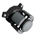
| − | + | | name = Kit (Logic Transmitter) | |
| − | + | | image = [[File:ItemKitLogicTransmitter.png]] | |
| − | + | | prefabhash = 1005397063 | |
| − | + | | prefabname = ItemKitLogicTransmitter | |
| − | + | | stacks = 5 | |
| − | + | | recipe_machine1 = Electronics Printer | |
| + | | recipe_cost1 = 2g [[Gold]], 1g [[Copper]], 3g [[Electrum]], 5g [[Silicon]] | ||
| + | | construct = [[Logic Transmitter]] | ||
}} | }} | ||
{{Structurebox | {{Structurebox | ||
| − | + | | name = Logic Transmitter | |
| − | + | | image = [[File:LogicTransmitter.png|thumb|Mounted Logic Transmitter]] | |
| − | + | | prefab_hash = -693235651 | |
| − | + | | prefab_name = StructureLogicTransmitter | |
| − | + | | power_usage = 50W | |
| − | + | | placed_on_grid = Small Grid | |
| − | + | | decon_with_tool1 = [[Hand Drill]] | |
| − | + | | placed_with_item = [[Kit (Logic Transmitter)]] | |
| + | | item_rec1 = [[Kit (Logic Transmitter)]] | ||
}} | }} | ||
| Line 26: | Line 29: | ||
The Logic Transmitter are used to transmit values in a logic network wirelessly. | The Logic Transmitter are used to transmit values in a logic network wirelessly. | ||
| − | The Logic Transmitter starts in | + | The Logic Transmitter starts in '''Passive''' mode and can be tied to '''Active''' transmitters, [[AIMEe]], [[Hardsuit]] and <s>[[Rover]]</s>. |
| − | While tied to anything but another Logic Transmitter is basically acts like a | + | While tied to anything but another Logic Transmitter is basically acts like a [[Kit_(Logic_I/O)#Logic_Mirror|Logic Mirror]], |
| − | + | except from far distance. | |
| − | If you set a Logic Transmitter to active you can write to the Setting variable on it to transmit to one or multiple Logic Transmitter that are tied to it in passive mode. | + | If you set a Logic Transmitter to active, you can write to the Setting variable on it to transmit that value to one or multiple Logic Transmitter that are tied to it in passive mode. |
| + | You tie a passive Logic Transmitter to an active Logic Transmitter by adjusting the screw on the passive Logic Transmitter until it matches the name of the active Logic Transmitter. NOTE: The active Logic transmitter must be on and active to show up as an option in the screw of the passive Logic Transmitter. You can then read the Setting variable from the passive Logic Transmitter. | ||
| + | |||
| + | This is the toggle button that can be manually used to change the Logic Transmitter '''Mode''': | ||
| + | [[File:LogicTransmitterActiveButton.png|400x300px|Example of where find the toggle button for the mode of the Logic Transmitter]] | ||
| + | |||
| + | The Logic Transmitter can also be tied to an [[Advanced Tablet]] which it then locally represents (mirrors) in the network. This allows playing of sounds on the tablet or to read out the tablet's values: The off/on state can be read as well as the current mode (representing which [[Cartridge]] is selected). Therefore, the tablet can now be used as a remote control. | ||
== Note == <!--T:8--> | == Note == <!--T:8--> | ||
* There seems to be no limit to the distance at which two devices can connect. | * There seems to be no limit to the distance at which two devices can connect. | ||
| + | * The Logic Transmitter have three data input ports and one for power. Due the fact that when the Logic Transmitter is in '''Active''' is used to mirror a signal from another Logic Transmitter, seems that all of the three input ports are not necessary on the same network (because they are all or output or input), but can be used for sharing the same value in different networks without mixing logic networks and/or having to build many Logic Transmitter for recieving the same value. | ||
| + | * The placed object prefabhash is -693235651. | ||
<!--T:15--> | <!--T:15--> | ||
| Line 47: | Line 58: | ||
| On || Boolean || | | On || Boolean || | ||
|- | |- | ||
| − | | Mode || Boolean || 0 for | + | | Mode || Boolean || 0 for '''Passive''', 1 for '''Active''' |
|- | |- | ||
| Setting || Any || Any setted o mirrored value from another device | | Setting || Any || Any setted o mirrored value from another device | ||
Latest revision as of 10:11, 30 April 2024
 | |
| Properties | |
|---|---|
| Stacks | Yes (5) |
| Recipes | |
| Electronics Printer | 2g Gold, 1g Copper, 3g Electrum, 5g Silicon |
| Logic | |
| Item Hash | 1005397063 |
| Item Name | ItemKitLogicTransmitter |
| Operation | |
|---|---|
| Power Usage | 50W |
| Prefab Hash | -693235651 |
| Prefab Name | StructureLogicTransmitter |
| Construction | |
| Placed with | Kit (Logic Transmitter) |
| Placed on | Small Grid |
| Stage 1 | |
| Deconstruction | |
| Deconstructed with | Hand Drill |
| Item received | Kit (Logic Transmitter) |
Description[edit]
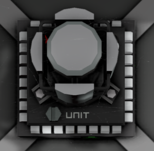
The Logic Transmitter are used to transmit values in a logic network wirelessly.
The Logic Transmitter starts in Passive mode and can be tied to Active transmitters, AIMEe, Hardsuit and Rover.
While tied to anything but another Logic Transmitter is basically acts like a Logic Mirror,
except from far distance.
If you set a Logic Transmitter to active, you can write to the Setting variable on it to transmit that value to one or multiple Logic Transmitter that are tied to it in passive mode. You tie a passive Logic Transmitter to an active Logic Transmitter by adjusting the screw on the passive Logic Transmitter until it matches the name of the active Logic Transmitter. NOTE: The active Logic transmitter must be on and active to show up as an option in the screw of the passive Logic Transmitter. You can then read the Setting variable from the passive Logic Transmitter.
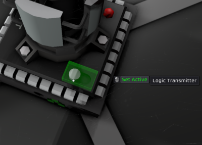
This is the toggle button that can be manually used to change the Logic Transmitter Mode:

The Logic Transmitter can also be tied to an Advanced Tablet which it then locally represents (mirrors) in the network. This allows playing of sounds on the tablet or to read out the tablet's values: The off/on state can be read as well as the current mode (representing which Cartridge is selected). Therefore, the tablet can now be used as a remote control.
Note[edit]
- There seems to be no limit to the distance at which two devices can connect.
- The Logic Transmitter have three data input ports and one for power. Due the fact that when the Logic Transmitter is in Active is used to mirror a signal from another Logic Transmitter, seems that all of the three input ports are not necessary on the same network (because they are all or output or input), but can be used for sharing the same value in different networks without mixing logic networks and/or having to build many Logic Transmitter for recieving the same value.
- The placed object prefabhash is -693235651.
Data Network Properties[edit]
These are all Data Network properties of this device.
Data Parameters[edit]
These are all parameters that can be written with a Logic Writer, Batch Writer, or Integrated Circuit (IC10).
| Parameter Name | Data Type | Description |
|---|---|---|
| On | Boolean | |
| Mode | Boolean | 0 for Passive, 1 for Active |
| Setting | Any | Any setted o mirrored value from another device |
Data Outputs[edit]
These are all parameters, that can be read with a Logic Reader or a Slot Reader. The outputs are listed in the order a Logic Reader's "VAR" setting cycles through them.
| Output Name | Data Type | Description |
|---|---|---|
| On | Boolean | If is enabled |
| Mode | Boolean | 0 for *Passive*, 1 for *Active* |
| Power | Boolean | If is taking power |
| PrefabHash | Integer | -693235651 |
| RequiredPower | Integer | Power required to work (50W) |
| Setting | Any | Any setted o mirrored value from another device |

