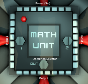
Carsten Milkau/NOT Gate
From Unofficial Stationeers Wiki
< User:Carsten MilkauRevision as of 06:13, 22 July 2018 by 89.16.148.86 (talk) (→Definition: names x and y for inputs/outputs in truth table)
Contents
NOT Gate
A NOT gate, sometimes also called inverter, is a circuit that outputs the value that was not input. It has a single input and output, and each can only take one of two pre-defined values (typically 0 and 1). Whatever the input value is selected, the output value will be the other of the two.
Definition
| inputs | outputs |
|---|---|
| x | y |
| 0 | 1 |
| 1 | 0 |
Connectors
- Input x: one of two values (0 or 1)
- Output y: the other of the two values
Implementation
NOT gates can often be avoided by modifying the circuit. For instance, an OR Gate with two NOT gates connected to its inputs and outputs can always be replaced by an AND gate with just one NOT gate connected.
Unfortunately, there is no single-component implementation of a NOT gate. However, if you happen to have a data signal with a known value (like a memory containing a constant), often you can feed this signal into a single component in order to turn it into a NOT gate.
Using A Less-Than Comparator
If you have a circuit available (e.g. a constant memory) that has a value b known to stay between 0 and 1 (but not 0), you can turn a Compare Unit into a logic NOT gate by comparing the input x to b, i.e.
y = (x < b)
| unit | unit type | connector/setting | source / value |
|---|---|---|---|
| compare 1 | Compare Unit | Input 1 | x (input) |
| Input 2 | b (constant or bounded value) | ||
| Operation Selector | Lesser | ||
| Output | y (output) |
Using An Equality Comparator
If you have a circuit output available that is known to be zero when the NOT gate is used (e.g. a constant memory), you can turn a Compare Unit into a logic NOT gate by comparing the input x to 0, i.e.
y = (x = 0)
| unit | unit type | connector/setting | source / value |
|---|---|---|---|
| compare 1 | Compare Unit | Input 1 | x (input) |
| Input 2 | 0 (constant) | ||
| Operation Selector | Equals | ||
| Output | y (output) |
Using Subtraction
If you do not use 0 and 1 as the two possible input values of the inverter, you can use subtraction for implementation. In this case, you need a constant that is exactly the mean of the two input values, i.e.
y = (m - x)
where m = (a + b)/2 is the mean of the two allowed input values, (called a and b here).
| unit | unit type | connector/setting | source/value |
|---|---|---|---|
| math 1 | Math Unit | Input 1 | x (input) |
| Input 2 | m (constant, see above) | ||
| Operation | Subtract | ||
| Output | y (output) |


