Filtration
From Unofficial Stationeers Wiki
 | |
| Operation | |
|---|---|
| Power Usage | 5w |
| Construction | |
| Placed with | Kit (Atmospherics) |
| Placed on | Small Grid |
| Stage 1 | |
| Deconstruction | |
| Deconstructed with | Hand Drill |
| Item received | Kit (Atmospherics) |
Contents
Description
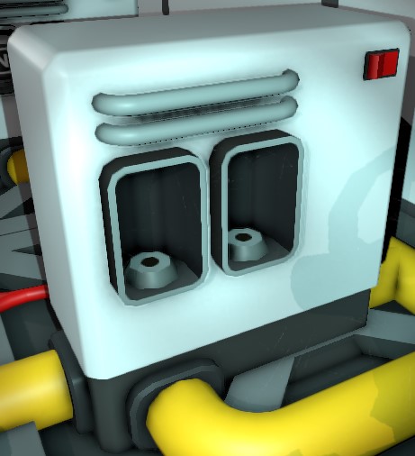
Used to separate gases from one pipe network into another using filters. Can filter up to two (2) gases at once. Guide (Filtration) provides additional information regarding the function, construction, and operation of a Filtration unit.
Usage
Once you have placed the Filtration Unit in your desired location, there are 3 separate connections that will need to be made:
- Input - Starting gas network that you want to filter from
- Output - Filtered gas
- Waste - Remaining unfiltered gas from the input
Place the appropriate filter(s) in the Filtration unit for the particular gas that your want to filter. Up to two filters can be placed into a filtration unit. If these are different types of filters, both types of gas will be filtered simultaneously. Placing two of the same type of filter in the unit does not increase filtration speed, it just provides redundancy for when one of the filters runs out.
Be aware that the filtration unit unrealistically has an infinitely powerful pump integrated into its output port. That means as long as it is turned on and there is gas to filter out from the input, it will pump that filtered out gas into the output pipe network (no matter how high the pressure in that output pipe network already is!). So eventually that pipe network will burst (around 60 MPa) unless you provide some sort of pop-off valve (e.g. a combination of a back-pressure regulator and a passive vent), use a pipe analyzer and some logic to turn the filtration unit off when a certain amount of pressure is exceeded in the output pipe network, or use the onboard IC10 and a data connection to the output (tank or pipe analyzer) to disable the unit when it reaches a certain threshold. Note that on-board IC10 chips do not execute when the unit is turned off, so an on-board IC10 is only capable of turning the unit off if output pressure is too high, it is not capable of turning the unit back on once output pressure drops.
As of patch patch 0.2.4218.19726, the filtration system processing speed is based the pressure differential between the input and output. The unit will output filtered gas equivalent to 10 L (one pipe segment) at a pressure equal to 1/40th of the partial pressure of the gas being filtered in the input. As an example, if the input is at 10 MPa and is 20% nitrogen (so partial pressure of nitrogen is 2 MPa), a filtration unit with a nitrogen filter will output, per tick, an amount of nitrogen equivalent to 50 kPa (2 MPa / 40) in a 10 L volume (~0.205 moles at 20 C). Since the partial pressure difference between the input and output directly impacts the speed, pressurizing the input is beneficial, as is attaching the output to a single pipe segment followed by an active Volume Pump set to maximum throughput (10 L/tick) to ensure the output is at minimum pressure.
Characteristics
- It has a manual power switch.
- It consumes 10W of Power per Tick when idle and 44W when active.
- It has a separate Power Port and Data Port.
- It has an on-board IC10 chip slot.
- It has a pipe port (labelled "Input") for the gas mixture from which the designated gas(es) will be filtered.
- It has a pipe port (labelled "Filtered") for the designated gas(es) that have been filtered. (This is in line with and directly opposite of the input)
- It has a pipe port (labelled "Unfiltered") for any remaining unfiltered gases. (This is to the side)
- It can filter up to 2 different gases at once by inserting two different filters.
Note: When using an I/O slot reader chip, the filter slots are labeled as slot 1, slot 2 and slot 3(IC), with 1 being the slot closer to the inlet. When using an IC chip, the slots are labeled as slot 0, slot1 and slot 2(IC).
User Interface
A Filtration unit provides the following user interface:
| Name | Type | Function |
|---|---|---|
| Filter (Right) | Slot 0 | Port for a gas filter. If gas of the same type is present in the incoming mixture, it will be redirected out the "Filtered" pipe port. |
| Filter (Left) | Slot 1 | Another Port for a gas filter that functions the same as its twin slot. May contain the same or a different filter. |
| v | Slot 2 | IC10 placed in filtration unit (has 2 Input/Outputs) |
| On | Switch | Switches Filtration unit between turned on or turned off. (On=1/Off=0) |
Data Network Properties
These are all Data Network properties of this device.
Data Parameters
These are all parameters that can be written with a Logic Writer, Batch Writer, or Integrated Circuit (IC10).
| Parameter Name | Data Type | Description |
|---|---|---|
| On | Boolean | Powers on the Filtration unit on when set to 1. Powers off when set to 0. |
| Open | Boolean | |
| Setting | Integer | |
| Lock | Boolean | |
| Mode | Boolean | 0: idle, 1: Active |
Data Outputs
These are all parameters, that can be read with a Logic Reader or a Slot Reader. The outputs are listed in the order a Logic Reader's "VAR" setting cycles through them.
| Output Name | Data Type | Description |
|---|---|---|
| Power | Boolean | Returns whether the Filtration unit is turned on and receives power. (0 for no, 1 for yes) |
| Open | Boolean | Returns whether the Filtration unit IC Slot cover is open or closed. (0 for closed, 1 for open) |
| Mode | Boolean | Returns whether the Filtration unit is active or idle (0 for idle, 1 for Active) |
| Error | Boolean | Returns whether the Filtration unit is flashing an error. (0 for no, 1 for yes) |
| Lock | Boolean | Returns whether the Filtration unit is locked. (0 for no, 1 for yes) |
| Setting | Integer | |
| Maximum | Integer | |
| Ratio | Float | |
| On | Boolean | Returns whether the Filtration unit is turned on. (0 for no, 1 for yes) |
| RequiredPower | Integer | Returns the current amount of power in Watts required by the Filtration unit. |
| PressureInput | Float | Input pressure in kilopascals |
| TemperatureInput | Float | Input temperature in kelvin |
| RatioOxygenInput | Float | Percentage of Oxygen in input as ratio between 0 and 1 |
| RatioCarbonDioxidenInput | Float | Percentage of Carbon Dioxide in input as ratio between 0 and 1 |
| RatioNitrogenInput | Float | Percentage of Nitrogen in input as ratio between 0 and 1 |
| RatioPollutantInput | Float | Percentage of Pollutant in input as ratio between 0 and 1 |
| RatioVolatilesInput | Float | Percentage of Volatiles in input as ratio between 0 and 1 |
| RatioWaterInput | Float | Percentage of Water in input as ratio between 0 and 1 |
| RatioNitrousOxideInput | Float | Percentage of Nitrous Oxide in input as ratio between 0 and 1 |
| TotalMolesInput | Float | Total quantity of gas in input measured in moles |
| PressureOutput | Float | Output pressure in kilopascals |
| TemperatureOutput | Float | Output temperature in kelvin |
| RatioOxygenOutput | Float | Percentage of Oxygen in output as ratio between 0 and 1 |
| RatioCarbonDioxidenOutput | Float | Percentage of Carbon Dioxide in output as ratio between 0 and 1 |
| RatioNitrogenOutput | Float | Percentage of Nitrogen in output as ratio between 0 and 1 |
| RatioPollutantOutput | Float | Percentage of Pollutant in output as ratio between 0 and 1 |
| RatioVolatilesOutput | Float | Percentage of Volatiles in output as ratio between 0 and 1 |
| RatioWaterOutput | Float | Percentage of Water in output as ratio between 0 and 1 |
| RatioNitrousOxideOutput | Float | Percentage of Nitrous Oxide in output as ratio between 0 and 1 |
| TotalMolesOutput | Float | Total quantity of gas in output measured in moles |
| PressureOutput2 | Float | Waste pressure in kilopascals |
| TemperatureOutput2 | Float | Waste temperature in kelvin |
| RatioOxygenOutput2 | Float | Percentage of Oxygen in waste as ratio between 0 and 1 |
| RatioCarbonDioxidenOutput2 | Float | Percentage of Carbon Dioxide in waste as ratio between 0 and 1 |
| RatioNitrogenOutput2 | Float | Percentage of Nitrogen in waste as ratio between 0 and 1 |
| RatioPollutantOutput2 | Float | Percentage of Pollutant in waste as ratio between 0 and 1 |
| RatioVolatilesOutput2 | Float | Percentage of Volatiles in waste as ratio between 0 and 1 |
| RatioWaterOutput2 | Float | Percentage of Water in waste as ratio between 0 and 1 |
| RatioNitrousOxideOutput2 | Float | Percentage of Nitrous Oxide in waste as ratio between 0 and 1 |
| TotalMolesOutput2 | Float | Total quantity of gas in waste measured in moles |
| CombustionInput | Float | |
| CombustionOutput | Float | |
| CombustionOutput2 | Float |
Slot Outputs
Slot 0 and 1 are the two gas filters. Slot 2 is the programmable chip
| Output Name | Data Type | Description |
|---|---|---|
| Occupied | Boolean | Returns whether the slot is occupied. (0 for no, 1 for yes) |
| OccupantHash | Integer | Returns the hash of the object in the slot. |
| Quantity | Integer | Returns the current quantity, such as stack size, of the item in the slot. |
| Damage | Integer | Returns the damage state of the item in the slot. |
| Class | Integer | Returns an integer representing the class of object. |
| MaxQuanity | Integer | Returns max stack size of the item in the slot. |
| PrefabHash | Integer | Returns the hash of the structure in the slot. |
