Difference between revisions of "Carsten Milkau/RS-Latch"
From Unofficial Stationeers Wiki
< User:Carsten Milkau
(→Using Logic Select Units) |
(→RS-latch: illegal state) |
||
| Line 1: | Line 1: | ||
== RS-latch == | == RS-latch == | ||
| − | An RS-latch is a circuit that stores which of its inputs was last "on". It has typically two inputs: input ''reset'' storing value "0" and input ''set'' storing value "1", hence the name. It can have multiple outputs, which typically differ mostly in their behavior when multiple inputs are "on" at the same time. | + | An RS-latch is a circuit that stores which of its inputs was last "on". It has typically two inputs: input ''reset'' storing value "0" and input ''set'' storing value "1", hence the name. It can have multiple outputs (possibly inverted), which typically differ mostly in their behavior when multiple inputs are "on" at the same time. Usually, it is considered illegal to set more than one input to "on", but sometimes this is used deliberately (e.g. when constructing an [[Edge-Triggered RS-Latch]]). |
{| class="wikitable" | {| class="wikitable" | ||
| Line 19: | Line 19: | ||
|} | |} | ||
| − | It is possible to define a variant with more than two values. | + | It is possible to define a variant with more than two values. Also, the values stored need not necessarily be 0 and 1. |
=== Connectors === | === Connectors === | ||
Revision as of 15:25, 18 July 2018
RS-latch
An RS-latch is a circuit that stores which of its inputs was last "on". It has typically two inputs: input reset storing value "0" and input set storing value "1", hence the name. It can have multiple outputs (possibly inverted), which typically differ mostly in their behavior when multiple inputs are "on" at the same time. Usually, it is considered illegal to set more than one input to "on", but sometimes this is used deliberately (e.g. when constructing an Edge-Triggered RS-Latch).
| inputs | outputs | ||||||
|---|---|---|---|---|---|---|---|
| reset | set | output1 (previous) | output2 (previous) | output1 | output2 | ||
| 0 | 0 | x | y | y | x | ||
| 0 | 1 | x | y | 0 | 0 | ||
| 1 | 0 | x | y | 1 | 1 | ||
| 1 | 1 | x | y | 0 | 1 | ||
It is possible to define a variant with more than two values. Also, the values stored need not necessarily be 0 and 1.
Connectors
- Enabled: if 1, store data, else do nothing.
- Data: input
- Output: stored value
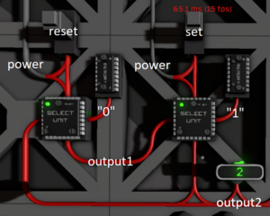
Using Logic Select Units
This RS-latch can store arbitrary values. It can also easily be extended to support more than two different values. It consists of a loop of Logic Select Units, each connected to a dedicated memory cell (or other data source). If all inputs are off, the values circulate in the loop. If one input is on, its corresponding value is read from the respective memory cell and replaces all values in the loop (unless an additional input is on).
| Unit name | Unit type | Connector / Setting | Source / Value |
|---|---|---|---|
| select 1 | Logic Select Unit | select | reset (input) |
| 0 (input 1) | select 2 | ||
| 1 (input 2) | "0" (constant) | ||
| output | output1 (output) | ||
| select 2 | Logic Select Unit | select | set (input) |
| 0 (input 1) | select 1 | ||
| 1 (input 2) | "1" (constant) | ||
| output | output2 (output) |

