Difference between revisions of "Kit (Switch)"
From Unofficial Stationeers Wiki
F1r3w4rr10r (talk | contribs) (Fill in more Structurebox parameters and add Itembox) |
|||
| Line 1: | Line 1: | ||
| − | |||
| − | |||
| − | |||
| − | |||
| − | |||
| − | |||
| − | |||
| − | |||
| − | |||
| − | |||
| − | |||
| − | |||
| − | |||
| − | |||
| − | |||
| − | |||
| − | |||
| − | |||
{{Structurebox | {{Structurebox | ||
| name = Switch | | name = Switch | ||
| image = [[File:Switch.jpg]] | | image = [[File:Switch.jpg]] | ||
| + | | power_usage = | ||
| + | | placed_with_item = [[Kit (Logic Switch)]] | ||
| + | | placed_on_grid = Small Grid | ||
| + | | decon_with_tool1 = [[Hand Drill]] | ||
| + | | item_rec1 = [[Kit (Logic Switch)]] | ||
| + | }} | ||
| + | {{Structurebox | ||
| + | | name = Lever | ||
| + | | image = [[File:Lever.jpg]] | ||
| + | | power_usage = | ||
| + | | placed_with_item = [[Kit (Logic Switch)]] | ||
| + | | placed_on_grid = Small Grid | ||
| + | | decon_with_tool1 = [[Hand Drill]] | ||
| + | | item_rec1 = [[Kit (Logic Switch)]] | ||
| + | }} | ||
| + | {{Structurebox | ||
| + | | name = Button | ||
| + | | image = [[File:Button.jpg]] | ||
| + | | power_usage = | ||
| + | | placed_with_item = [[Kit (Logic Switch)]] | ||
| + | | placed_on_grid = Small Grid | ||
| + | | decon_with_tool1 = [[Hand Drill]] | ||
| + | | item_rec1 = [[Kit (Logic Switch)]] | ||
| + | }} | ||
| + | {{Structurebox | ||
| + | | name = Dial | ||
| + | | image = [[File:Dial.jpg]] | ||
| power_usage = | | power_usage = | ||
| placed_with_item = [[Kit (Logic Switch)]] | | placed_with_item = [[Kit (Logic Switch)]] | ||
| Line 26: | Line 35: | ||
| item_rec1 = [[Kit (Logic Switch)]] | | item_rec1 = [[Kit (Logic Switch)]] | ||
}} | }} | ||
| + | |||
| + | The Logic Switch gives players the ability to add controls to control circuits without requiring tools. | ||
| + | |||
| + | == Switch == | ||
Toggles output value between 0 and 1. | Toggles output value between 0 and 1. | ||
| Line 34: | Line 47: | ||
* Bottom: Data Output | * Bottom: Data Output | ||
| − | |||
== Lever == | == Lever == | ||
| − | |||
| − | |||
| − | |||
| − | |||
| − | |||
| − | |||
| − | |||
| − | |||
| − | |||
Toggles output value between 0 and 1. | Toggles output value between 0 and 1. | ||
| Line 53: | Line 56: | ||
* Bottom: Data Output | * Bottom: Data Output | ||
| − | |||
== Button == | == Button == | ||
| − | |||
| − | |||
| − | |||
| − | |||
| − | |||
| − | |||
| − | |||
| − | |||
| − | |||
Sends a pulse of 0.5(i think) seconds long of value 1. | Sends a pulse of 0.5(i think) seconds long of value 1. | ||
| Line 72: | Line 65: | ||
* Bottom: Data Output | * Bottom: Data Output | ||
| − | |||
== Dial == | == Dial == | ||
| − | |||
| − | |||
| − | |||
| − | |||
| − | |||
| − | |||
| − | |||
| − | |||
| − | |||
Allows user to select a value between 0 and the maximum set by use of screws. | Allows user to select a value between 0 and the maximum set by use of screws. | ||
Revision as of 08:12, 9 July 2018
 | |
| Operation | |
|---|---|
| Construction | |
| Placed with | Kit (Logic Switch) |
| Placed on | Small Grid |
| Stage 1 | |
| Deconstruction | |
| Deconstructed with | Hand Drill |
| Item received | Kit (Logic Switch) |
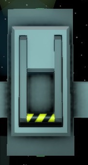 | |
| Operation | |
|---|---|
| Construction | |
| Placed with | Kit (Logic Switch) |
| Placed on | Small Grid |
| Stage 1 | |
| Deconstruction | |
| Deconstructed with | Hand Drill |
| Item received | Kit (Logic Switch) |
 | |
| Operation | |
|---|---|
| Construction | |
| Placed with | Kit (Logic Switch) |
| Placed on | Small Grid |
| Stage 1 | |
| Deconstruction | |
| Deconstructed with | Hand Drill |
| Item received | Kit (Logic Switch) |
 | |
| Operation | |
|---|---|
| Construction | |
| Placed with | Kit (Logic Switch) |
| Placed on | Small Grid |
| Stage 1 | |
| Deconstruction | |
| Deconstructed with | Hand Drill |
| Item received | Kit (Logic Switch) |
The Logic Switch gives players the ability to add controls to control circuits without requiring tools.
Contents
Switch
Toggles output value between 0 and 1.
Connectors
- Top: Data Output
- Bottom: Data Output
Lever
Toggles output value between 0 and 1.
Connectors
- Top: Data Output
- Bottom: Data Output
Button
Sends a pulse of 0.5(i think) seconds long of value 1.
Connectors
- Top: Data Output
- Bottom: Data Output
Dial
Allows user to select a value between 0 and the maximum set by use of screws.
Connectors
- Bottom: Data Output
Screws
- Bottom Left: Decrease maximum possible value to be set by dial.
- Bottom Right: Increase maximum possible value to be set by dial.
