Difference between revisions of "Kit (Logic I/O)"
From Unofficial Stationeers Wiki
m (Batch Reader & Slot Reader now on stable) |
|||
| Line 42: | Line 42: | ||
| name = Batch Reader | | name = Batch Reader | ||
| image = [[File:BatchReader.jpg]] | | image = [[File:BatchReader.jpg]] | ||
| − | |||
| power_usage = 10W | | power_usage = 10W | ||
| placed_with_item = [[Kit (Logic I/O)]] | | placed_with_item = [[Kit (Logic I/O)]] | ||
| Line 108: | Line 107: | ||
== Slot Reader == | == Slot Reader == | ||
| − | |||
| − | |||
=== Connectors === | === Connectors === | ||
| Line 124: | Line 121: | ||
== Batch Reader == | == Batch Reader == | ||
| − | |||
| − | |||
=== Connectors === | === Connectors === | ||
Revision as of 11:54, 5 July 2018
 | |
| Operation | |
|---|---|
| Power Usage | 10W |
| Construction | |
| Placed with | Kit (Logic I/O) |
| Placed on | Small Grid, On Frames |
| Stage 1 | |
| Deconstruction | |
| Deconstructed with | Hand Drill |
 | |
| Operation | |
|---|---|
| Power Usage | 10W |
| Construction | |
| Placed with | Kit (Logic I/O) |
| Placed on | Small Grid, On Frames |
| Stage 1 | |
| Deconstruction | |
| Deconstructed with | Hand Drill |
 | |
| Operation | |
|---|---|
| Power Usage | 10W |
| Construction | |
| Placed with | Kit (Logic I/O) |
| Placed on | Small Grid, On Frames |
| Stage 1 | |
| Deconstruction | |
| Deconstructed with | Hand Drill |
 | |
| Operation | |
|---|---|
| Power Usage | 10W |
| Construction | |
| Placed with | Kit (Logic I/O) |
| Placed on | Small Grid, On Frames |
| Stage 1 | |
| Deconstruction | |
| Deconstructed with | Hand Drill |
 | |
| Operation | |
|---|---|
| Power Usage | 10W |
| Construction | |
| Placed with | Kit (Logic I/O) |
| Placed on | Small Grid, On Frames |
| Stage 1 | |
| Deconstruction | |
| Deconstructed with | Hand Drill |
 | |
| Operation | |
|---|---|
| Power Usage | 10W |
| Construction | |
| Placed with | Kit (Logic I/O) |
| Placed on | Small Grid, On Frames |
| Stage 1 | |
| Deconstruction | |
| Deconstructed with | Hand Drill |
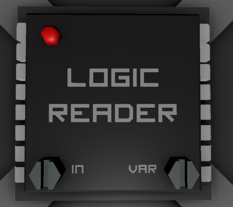
The Logic Input/Output Unit is used to Read (input) data from any machine with a data port connected through the data network, or Write (output) data to any machine with a data port connected to trough the data network. The Input, Output and Power networks can be completely separated.
Contents
[hide]Logic Reader
Connectors
- Left: Data Input
- Top: Power Input (10w)
- Right: Data Output
Screws
- Left: Input Selector. Click with Screwdriver to select from which machine to read from. Only machines with a data port connected though the cables connected to the left port can be read from.
- Right: Variable Selector: Click to select what Variable to output into the network on the right. Different machines will have different available variables to read from.
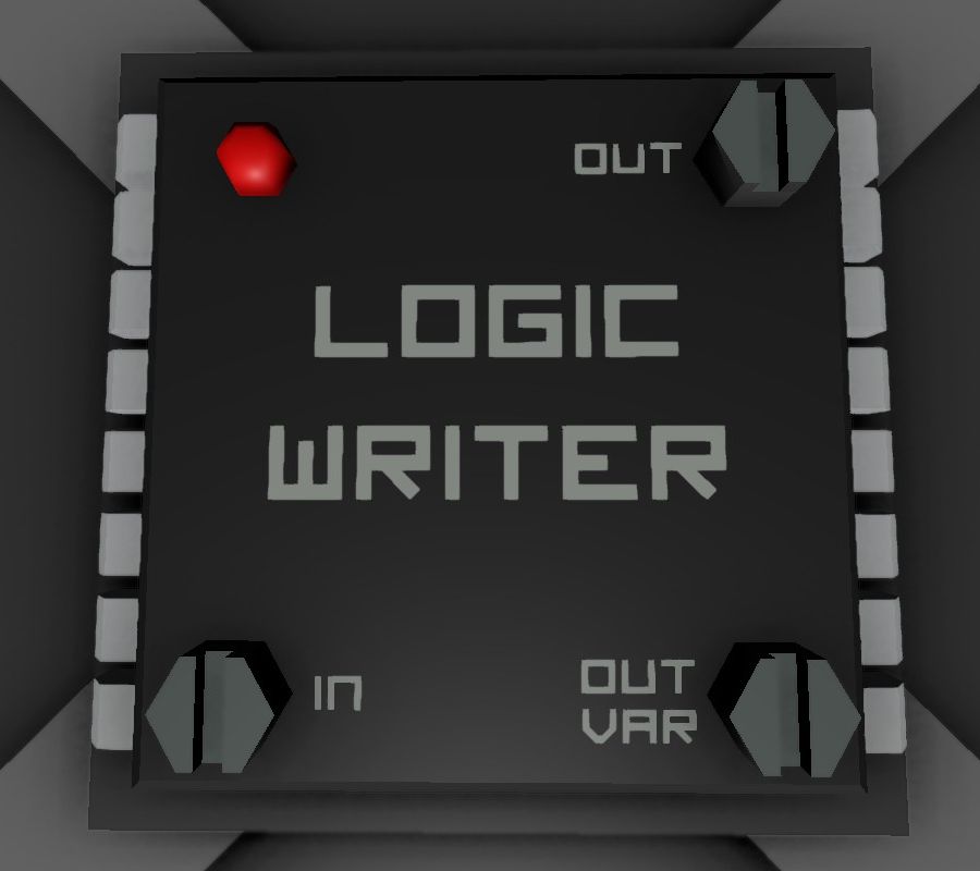
Logic Writer
Connectors
- Left: Data Input
- Top: Power Input (10w)
- Right: Data Output
Screws
- Bottom Left: Variable Input Selector: Click with Screwdriver to select the value to input. This can be directly from a machine, another logic circuit, a computer, etc.
- Top Right: Machine Write Selector. Click to select what machine to write to. Only machines with a data port connected though the cables connected to the right port can be written to.
- Bottom Right: Variable Selector: Click to select what variable to write to the machine. The value written will be what is captured by the Variable Input Selector.
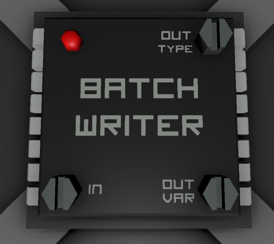
Batch Writer
The Batch Writer writes to all conected devices of a device type. For example: One can control all digital valves connected in its network with a single Batch Writer.
Connectors
- Left: Data Input
- Top: Power Input (10w)
- Right: Data Output
Screws
- Bottom Left: Variable Input Selector: Click with Screwdriver to select the value to input. This can be directly from a machine, another logic circuit, a computer, etc.
- Top Right: Machine Type Selector. Click to select what machine type to write to. All machines of that type will recieve the exact same data. For example selecting Solar Panel will write to all solar panels on the network.
- Bottom Right: Variable Selector: Click to select what variable to write to the machines. The value written will be what is captured by the Variable Input Selector.
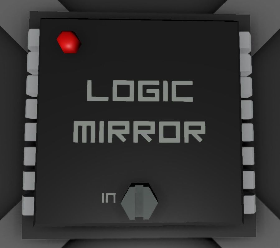
Logic Mirror
Connectors
- Left: Mirrored Device
- Top: Power Input (10w)
- Right: Data Input/Output
Screws
- Centre: Variable Mirroring Selector: Click with Screwdriver to select the device to mirror. This can be any machine, logic circuit, computer, etc.
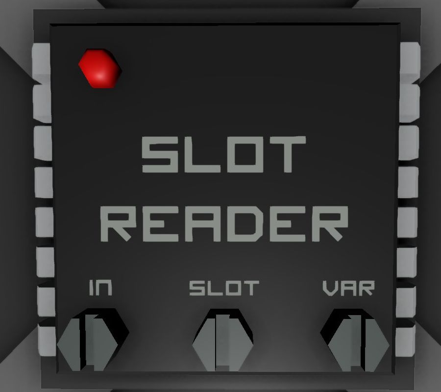
Slot Reader
Connectors
- Left: Data Input
- Top: Power Input (10w)
- Right: Data Output
Screws
- Left: Variable Input Selector: Click with Screwdriver to select the value to input. This can be from any device that has inventory slots, etc.
- Centre: Slot Selector: Click to Select which slot to read from.
- Right: Variable Selector: Click to select what variable to output into the network on the right.
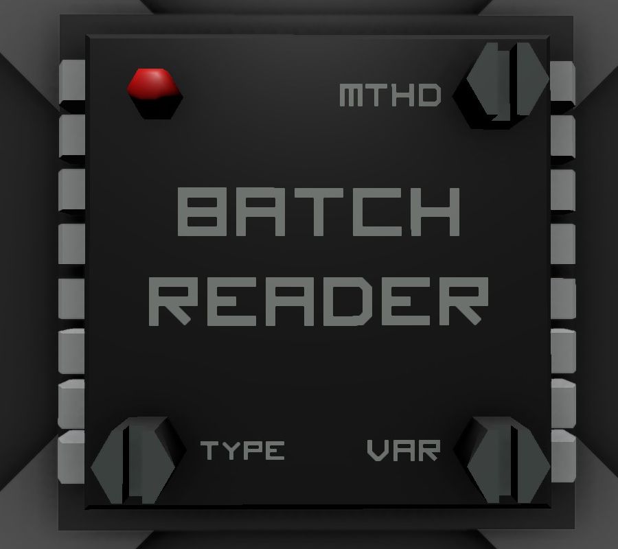
Batch Reader
Connectors
- Left: Data Input
- Top: Power Input (10w)
- Right: Data Output
Screws
- Bottom Left: Variable Input Selector: Click with Screwdriver to select from which machine type to read from.
- Top Right: Method Selector. Click to select by which method to pull data.
- Bottom Right: Variable Selector: Click to select what variable to output into the network on the right.
