Difference between revisions of "Air Conditioner"
From Unofficial Stationeers Wiki
(Add missing data outputs) |
|||
| Line 13: | Line 13: | ||
<!--T:1--> | <!--T:1--> | ||
==Description== | ==Description== | ||
| − | Used to lower or raise the temperature of [[Gas]] in a [[Pipes|pipe]] network. It has a range of - | + | Used to lower or raise the temperature of [[Gas]] in a [[Pipes|pipe]] network. It has a range of -270 through 999 Celsius for the temperature output. [[Guide (Air Conditioning)]] provides additional information regarding the function, construction, and operation of an Air Conditioner. |
==Usage== | ==Usage== | ||
Revision as of 13:42, 7 August 2023
 | |
| Operation | |
|---|---|
| Power Usage | 10 W when idle 355 W when running |
| Construction | |
| Placed with | Kit (Atmospherics) |
| Placed on | Small Grid |
| Stage 1 | |
| Deconstruction | |
| Deconstructed with | Hand Drill |
| Item received | Kit (Atmospherics) |
Contents
Description
Used to lower or raise the temperature of Gas in a pipe network. It has a range of -270 through 999 Celsius for the temperature output. Guide (Air Conditioning) provides additional information regarding the function, construction, and operation of an Air Conditioner.
Usage
Once you have placed the Air Conditioner Unit in your desired location, there are 3 separate connections that will need to be made:
- Input - The starting gas that is desired to be cooled or heated
- Output - The exhausted gas after energy has been transferred to or from the Coolant in the waste pipe network
- Waste - Connection where energy is transferred to the Coolant in the pipe network
Cooling
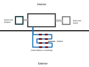
The Air Conditioner will take the excess heat from the input gas and transfer it to the Coolant stored in the waste pipe network. Attached to the waste pipe network should be either Pipe Radiators or Medium Radiators to either convect heat in a pressurized environment or radiate heat in a vacuum environment. Make the pipe network loop on back to the waste port after the radiators for slightly better efficiency.
Heating
Ensuring the temperature of the coolant is higher than the temperature of the gas you want attempting to heat will allow the Air Conditioner Unit to heat the gas being run through the input port. Attaching a Pipe Heater is a quick method of raising the temperature of the coolant in the waste pipe network.
Waste Pipe Network
A connected gas pipe network containing any desired Coolant. The Air Conditioner Unit will draw or expel heat from/to the coolant to adjust the input gas temperature to match the selected output temperature.
If the waste pipe network is below 100kPa pressure upon starting the Air Conditioning Unit, it will divert inputted gas from the output port to the waste port until the minimum 100kPa pressure threshold is met within the waste pipe network.
Characteristics
- It has a manual power switch.
- It consumes 10W of Power per Tick when idle.
- It consumes 350W of Power per Tick when active.
- Basically, both speed and true efficiency is best at small temperature differences. For large temperature differences, more airco units need to be put in series.
- It has a separate Power Port and Data Port.
- It has a touchpad that provides manual temperature control.
- It has a pipe port (labelled "Input") for the gases that will be heated or cooled to the designated temperature.
- It has a pipe port (labelled "Output") for the gases that have been heated or cooled to the designated temperature.
- It has a pipe port (labelled "Waste") for gases to or from which heat will be transferred to raise or lower the input gases' temperature.
- Performance drops significantly if the temperature difference becomes too great. Chaining multiple systems, where each airco cooling/heating the waste pipe of the previous, seems the best way to reach large temperature differences.
- Efficiency changes the effective cooling or heating speed. If it is due to decreasing the volume per tick or J per tick, I do not know.
Efficiency is lost if:
- you want to cool and the waste temp is higher than the input temp (and vice versa)
- Input temperature is outside optimal working temperature from -50 to 100 C.
- input temperature at 400°C ~ 33% efficency
- input temperature at 600°C ~ 10% efficency
- input temperature at 1000°C ~ 0% efficiency
- Efficiency drop due to temperature difference between input and waste is not linear. From 0 difference, efficiency ramps down, after goes straight, and finally levels around T diff ~= 100 (asymptote?) reaching 0% efficiency beyond. Treating it linear anyway, roughly speaking, the efficiency drops 1% per unit temperature difference.
- Efficiency drop due to temperature difference can be negative (>100%), if heat flow is in the working direction, but is low.
Below, I do not know if is still true after the atmospherics update.
- The amount of gas processed in each tick depends on 2 variables: input temperature and the number of input pipe segments
- The formula used appears to be: n x T x S x R = 10123
- n = the number of moles of gas processed
- T = input pipe temperature
- S = number of input pipe segments (this is an analog for input pipe volume)
- R = 8.3144
- The formula used appears to be: n x T x S x R = 10123
- Once the amount of processed gas is known, the output temperature can be calculated
- T2 = T1 - 6000 / (n x H)
- T2 = output processed gas temperature
- T1 = input pipe temperature
- n = number of moles of processed gas, see above
- H = heat capacity of the gas in J/(mol x K), i.e. for CO2 it's 28.2 J/mol*K
- T2 = T1 - 6000 / (n x H)
User Interface
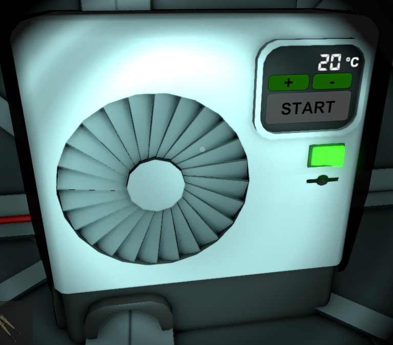
An Air Conditioner provides the following user interface:
| Name | Type | Function |
|---|---|---|
| Temperature | Display | Displays the current output temperature setting |
| + | Touchkey | Increase the current output temperature setting by 10°C and by 1°C with the Quantity Modifier key pressed. |
| - | Touchkey | Decrease the current output temperature setting by 10°C and by 1°C with the Quantity Modifier key pressed. |
| Start | Touchkey | Switches Air Conditioner between idle and active. |
| On/Off | Switch | Switches Air Conditioner between turned on or turned off. |
Data Network Properties
These are all Data Network properties of this device.
Data Parameters
These are all parameters that can be written with a Logic Writer, Batch Writer, or Integrated Circuit (IC10).
| Parameter Name | Data Type | Description |
|---|---|---|
| Open | Boolean | Opens the front IC Slot cover when set to 1. CLoses when set to 0. |
| Mode | Integer | Activates the Air Conditioner when set to 1. Idles it when set to 0. |
| Lock | Boolean | Locks the Air Conditioner when set to 1. Unlocks it when set to 0. |
| On | Boolean | Powers on the Air Conditioner on when set to 1. Powers off when set to 0. |
Data Outputs
These are all parameters, that can be read with a Logic Reader or a Slot Reader. The outputs are listed in the order a Logic Reader's "VAR" setting cycles through them.
| Output Name | Data Type | Description |
|---|---|---|
| Power | Boolean | Returns whether the Air Conditioner is turned on and receives power. (0 for no, 1 for yes) |
| Open | Boolean | Returns whether the Air Conditioner's IC Slot cover is open or closed. (0 for closed, 1 for open) |
| Mode | Integer | Returns whether the Air Conditioner is active or idle. (0 for no, 1 for yes) |
| Error | Boolean | Returns whether the Air Conditioner is flashing an error. (0 for no, 1 for yes) |
| Lock | Boolean | Returns whether the Air Conditioner is locked. (0 for no, 1 for yes) |
| Setting | Float | Target temperature setpoint in kelvin |
| Maximum | Float | Maximum temperature in kelvin |
| Ratio | Float | |
| On | Boolean | Returns whether the Air Conditioner is turned on. (0 for no, 1 for yes) |
| RequiredPower | Integer | Returns the current amount of power in Watts required by the Air Conditioner. |
| PressureInput | Float | Input pressure in kilopascals |
| TemperatureInput | Float | Input temperature in kelvin |
| RatioOxygenInput | Float | Percentage of Oxygen in input as ratio between 0 and 1 |
| RatioCarbonDioxidenInput | Float | Percentage of Carbon Dioxide in input as ratio between 0 and 1 |
| RatioNitrogenInput | Float | Percentage of Nitrogen in input as ratio between 0 and 1 |
| RatioPollutantInput | Float | Percentage of Pollutant in input as ratio between 0 and 1 |
| RatioVolatilesInput | Float | Percentage of Volatiles in input as ratio between 0 and 1 |
| RatioWaterInput | Float | Percentage of Water in input as ratio between 0 and 1 |
| RatioNitrousOxideInput | Float | Percentage of Nitrous Oxide in input as ratio between 0 and 1 |
| TotalMolesInput | Float | Total quantity of gas in input measured in moles |
| PressureOutput | Float | Output pressure in kilopascals |
| TemperatureOutput | Float | Output temperature in kelvin |
| RatioOxygenOutput | Float | Percentage of Oxygen in output as ratio between 0 and 1 |
| RatioCarbonDioxidenOutput | Float | Percentage of Carbon Dioxide in output as ratio between 0 and 1 |
| RatioNitrogenOutput | Float | Percentage of Nitrogen in output as ratio between 0 and 1 |
| RatioPollutantOutput | Float | Percentage of Pollutant in output as ratio between 0 and 1 |
| RatioVolatilesOutput | Float | Percentage of Volatiles in output as ratio between 0 and 1 |
| RatioWaterOutput | Float | Percentage of Water in output as ratio between 0 and 1 |
| RatioNitrousOxideOutput | Float | Percentage of Nitrous Oxide in output as ratio between 0 and 1 |
| TotalMolesOutput | Float | Total quantity of gas in output measured in moles |
| PressureOutput2 | Float | Waste pressure in kilopascals |
| TemperatureOutput2 | Float | Waste temperature in kelvin |
| RatioOxygenOutput2 | Float | Percentage of Oxygen in waste as ratio between 0 and 1 |
| RatioCarbonDioxidenOutput2 | Float | Percentage of Carbon Dioxide in waste as ratio between 0 and 1 |
| RatioNitrogenOutput2 | Float | Percentage of Nitrogen in waste as ratio between 0 and 1 |
| RatioPollutantOutput2 | Float | Percentage of Pollutant in waste as ratio between 0 and 1 |
| RatioVolatilesOutput2 | Float | Percentage of Volatiles in waste as ratio between 0 and 1 |
| RatioWaterOutput2 | Float | Percentage of Water in waste as ratio between 0 and 1 |
| RatioNitrousOxideOutput2 | Float | Percentage of Nitrous Oxide in waste as ratio between 0 and 1 |
| TotalMolesOutput2 | Float | Total quantity of gas in waste measured in moles |
| OperationalTemperatureEfficiency | Float | Ratio between 0 and 1 indicating that the unit is operating within its optimal temperature range |
| TemperatureDifferentialEfficiency | Float | Ratio between 0 and 1 that approaches 0 as the difference in temperature between the input and waste is too high |
| PressureEfficiency | Float | Ratio between 0 and 1 with efficiency reaching 1 when both input and waste pressure > 111.4575 kPa |

