Difference between revisions of "Kit (Logic Processor)"
From Unofficial Stationeers Wiki
(Provided the details of newly added operation in Kit (Logic Processor) (Math)) |
|||
| (3 intermediate revisions by 2 users not shown) | |||
| Line 3: | Line 3: | ||
| name = Math Unit | | name = Math Unit | ||
| image = [[File:MathUnit.png|Logic Processor Variation: Math Unit]] | | image = [[File:MathUnit.png|Logic Processor Variation: Math Unit]] | ||
| − | | power_usage = | + | | power_usage = 10W |
| placed_with_item = [[Kit (Logic Processor)]] | | placed_with_item = [[Kit (Logic Processor)]] | ||
| − | | placed_on_grid = Small Grid, On Frames | + | | placed_on_grid = Small Grid, On Frames, resources_needed = 1g gold, 1 copper |
| + | |||
| decon_with_tool1 = [[Hand Drill]] | | decon_with_tool1 = [[Hand Drill]] | ||
}} | }} | ||
| Line 11: | Line 12: | ||
| name = Compare Unit | | name = Compare Unit | ||
| image = [[File:CompareUnit.png|Logic Processor Variant: Compare Unit]] | | image = [[File:CompareUnit.png|Logic Processor Variant: Compare Unit]] | ||
| − | | power_usage = | + | | power_usage = 10W |
| placed_with_item = [[Kit (Logic Processor)]] | | placed_with_item = [[Kit (Logic Processor)]] | ||
| placed_on_grid = Small Grid, On Frames | | placed_on_grid = Small Grid, On Frames | ||
| Line 19: | Line 20: | ||
| name = Select Unit | | name = Select Unit | ||
| image = [[File:SelectUnit.png|Logic Processor Variant: Select Unit]] | | image = [[File:SelectUnit.png|Logic Processor Variant: Select Unit]] | ||
| − | | power_usage = | + | | power_usage = 10W |
| placed_with_item = [[Kit (Logic Processor)]] | | placed_with_item = [[Kit (Logic Processor)]] | ||
| placed_on_grid = Small Grid, On Frames | | placed_on_grid = Small Grid, On Frames | ||
| Line 27: | Line 28: | ||
| name = Min/Max Unit | | name = Min/Max Unit | ||
| image = [[File:MinMaxUnit.png|Logic Processor Variation: Min/Max Unit]] | | image = [[File:MinMaxUnit.png|Logic Processor Variation: Min/Max Unit]] | ||
| − | | power_usage = | + | | power_usage = 10W |
| placed_with_item = [[Kit (Logic Processor)]] | | placed_with_item = [[Kit (Logic Processor)]] | ||
| placed_on_grid = Small Grid, On Frames | | placed_on_grid = Small Grid, On Frames | ||
| Line 36: | Line 37: | ||
| image = [[File:MathUnary.png|Logic Processor Variation: Unary Math Unit]] | | image = [[File:MathUnary.png|Logic Processor Variation: Unary Math Unit]] | ||
| − | | power_usage = | + | | power_usage = 10W |
| + | | placed_with_item = [[Kit (Logic Processor)]] | ||
| + | | placed_on_grid = Small Grid, On Frames | ||
| + | | decon_with_tool1 = [[Hand Drill]] | ||
| + | }} | ||
| + | {{Structurebox | ||
| + | | name = Gate Unit | ||
| + | | image = [[File:GateUnit.png|Logic Processor Variation: Logic Gate Unit]] | ||
| + | |||
| + | | power_usage = 10W | ||
| placed_with_item = [[Kit (Logic Processor)]] | | placed_with_item = [[Kit (Logic Processor)]] | ||
| placed_on_grid = Small Grid, On Frames | | placed_on_grid = Small Grid, On Frames | ||
| Line 154: | Line 164: | ||
* Exp: The natural exponential function of the input. e raised to the power of the input. | * Exp: The natural exponential function of the input. e raised to the power of the input. | ||
* Round: Rounds the input to the closest whole integer. | * Round: Rounds the input to the closest whole integer. | ||
| + | |||
| + | |||
| + | == Logic Gate Unit == | ||
| + | |||
| + | === Connectors === | ||
| + | |||
| + | * Top: Power | ||
| + | * Left: Input 1 | ||
| + | * Right: Input 2 | ||
| + | * Bottom: Output | ||
| + | |||
| + | === Screws (options) === | ||
| + | |||
| + | * Top: Operation Selector. Click with the Screwdriver to select the logic operation to be performed on the two inputs | ||
| + | * Left: Input Selector. Click with the Screwdriver to select the input data. | ||
| + | * Right: Input Selector. Click with the Screwdriver to select the input data. | ||
| + | |||
| + | === Available Operations === | ||
| + | |||
| + | '''Note:''' The operations as described below are '''logical''' as opposed to '''bitwise'''. All non-zero inputs are effectively treated as '''One''' or '''True''', therefore an '''OR''' operation where input 1 is the value of '''four''' and input 2 is the value of '''one''' will result in an output of '''1''' as opposed to '''5''' as it would be in a bitwise OR. | ||
| + | |||
| + | * OR: Where '''either''' inputs are '''True''' the output will be '''True (1)''', otherwise the output will be '''False (0)''' | ||
| + | * AND: Where '''both''' inputs are '''True''' the output will be '''True (1)''', otherwise the output will be '''False (0)''' | ||
| + | * XOR: Similar to the '''OR''' operation with the exception that if '''both''' inputs are '''True''', the output will be '''False (0)''' | ||
| + | |||
| + | The following operations simply '''invert''' the output of the aforementioned '''OR''', '''AND''' and '''XOR''' operations. | ||
| + | |||
| + | * NOR: Inverted '''OR''' output. If a standard '''OR''' operation outputs '''True (1)''', this operation will output '''False (0)''' and visa-versa. | ||
| + | * NAND: Inverted '''AND''' output. If a standard '''AND''' operation outputs '''True (1)''', this operation will output '''False (0)''' and visa-versa. | ||
| + | * XNOR: Inverted '''XOR''' output. If a standard '''XOR''' operation outputs '''True (1)''', this operation will output '''False (0)''' and visa-versa. | ||
Latest revision as of 09:35, 31 July 2022
 | |
| Operation | |
|---|---|
| Power Usage | 10W |
| Construction | |
| Placed with | Kit (Logic Processor) |
| Placed on | Small Grid, On Frames, resources_needed = 1g gold, 1 copper |
| Stage 1 | |
| Deconstruction | |
| Deconstructed with | Hand Drill |
 | |
| Operation | |
|---|---|
| Power Usage | 10W |
| Construction | |
| Placed with | Kit (Logic Processor) |
| Placed on | Small Grid, On Frames |
| Stage 1 | |
| Deconstruction | |
| Deconstructed with | Hand Drill |
 | |
| Operation | |
|---|---|
| Power Usage | 10W |
| Construction | |
| Placed with | Kit (Logic Processor) |
| Placed on | Small Grid, On Frames |
| Stage 1 | |
| Deconstruction | |
| Deconstructed with | Hand Drill |
 | |
| Operation | |
|---|---|
| Power Usage | 10W |
| Construction | |
| Placed with | Kit (Logic Processor) |
| Placed on | Small Grid, On Frames |
| Stage 1 | |
| Deconstruction | |
| Deconstructed with | Hand Drill |
 | |
| Operation | |
|---|---|
| Power Usage | 10W |
| Construction | |
| Placed with | Kit (Logic Processor) |
| Placed on | Small Grid, On Frames |
| Stage 1 | |
| Deconstruction | |
| Deconstructed with | Hand Drill |
 | |
| Operation | |
|---|---|
| Power Usage | 10W |
| Construction | |
| Placed with | Kit (Logic Processor) |
| Placed on | Small Grid, On Frames |
| Stage 1 | |
| Deconstruction | |
| Deconstructed with | Hand Drill |
The Logic Processor is a multi-purpose Logic Circuit unit that has variants, all related to some mathematical operation.
Contents
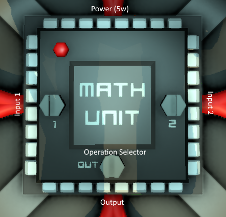
Math Unit[edit]
Connectors[edit]
- Top: Power
- Left: Input 1
- Right: Input 2
- Bottom: Output
Screws (options)[edit]
- Left: Input 1 Selector. Click with screwdriver to select the "left" operand
- Right: Input 2 Selector. Click with screwdriver to select the "right" operand
- Bottom: Operation Selector. Click with screwdriver to select what operation to run on the 2 inputs.
Available Operations[edit]
- Add: Adds the two inputs together. (output = i1 + i2)
- Subtract: Substract the right operand from the left one. (output: i1 - i2)
- Multiply: Multiplies the two inputs (output = i1 x i2)
- Divide: Divides the left operand by the right operand (output = i1 / i2)
- Mod: Runs the modulo function such that output = i1 % i2, where the output is the remainder of the division of the left operand by the right operand.
- Atan2: Arc Tangent of y/x. (Inverse Tan of [ i2 / i1 ] ).
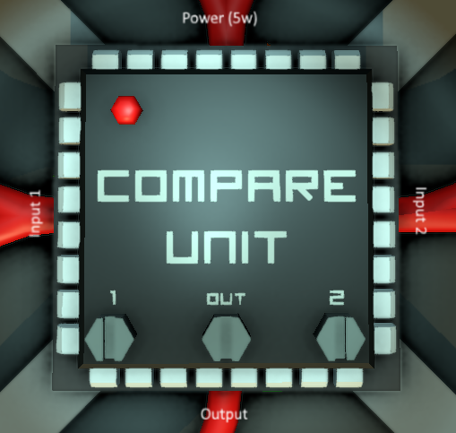
Compare Unit[edit]
Connectors[edit]
- Top: Power
- Left: Input 1
- Right: Input 2
- Bottom: Output
Screws (options)[edit]
- Bottom Left: Input 1 Selector. Click with screwdriver to select the "left" operand
- Bottom Right: Input 2 Selector. Click with screwdriver to select the "right" operand
- Bottom Center: Operation Selector. Click with screwdriver to select what operation to run on the 2 inputs.
Available Operations[edit]
Note: This is a floating point comparison and is very precise!
- Equals: Outputs 1 (true) if Input 1 is exactly equal to Input 2, otherwise outputs 0 (false).
- NotEquals: Outputs 1 (true) if Input 1 has a different value than Input 2, otherwise outputs 0 (false).
- Greater: Outputs 1 (true) if Input 1 is greater than Input 2, otherwise outputs 0 (false).
- Lesser: Outputs 1 (true) if Input 1 is smaller/lesser than Input 2, otherwise outputs 0 (false).
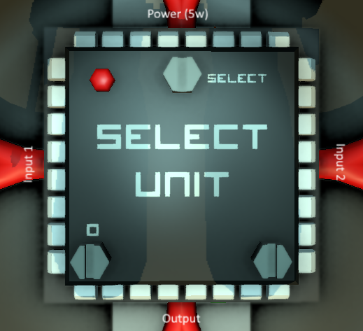
Select Unit[edit]
Connectors[edit]
- Top: Power and Selector Input
- Left: Input 1
- Right: Input 2
- Bottom: Output
Screws (options)[edit]
- Top: Selector Input. Use Screwdriver to select what input is used to flip the selection. This should usually be a unit that outputs a true/false value (0 for false, 1 for true), such as a Logic Compare unit.
- Bottom Left: Input 1 Selector. Use Screwdriver to select what value to use when the Selector Input value is 0 (false).
- Bottom Right: Input 2 Selector. Use Screwdriver to select what value to use when the Selector Input value is 1 (true).
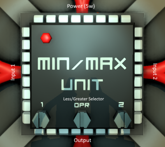
Min/Max Unit[edit]
Connectors[edit]
- Top: Power
- Left: Input 1
- Right: Input 2
- Bottom: Output
Screws (options)[edit]
- Bottom Left: Input 1 Selector. Click with screwdriver to select the "left" operand
- Bottom Right: Input 2 Selector. Click with screwdriver to select the "right" operand
- Bottom Center: Operation Selector. Click with screwdriver to select what operation to run on the 2 inputs.
Available Operations[edit]
- Less: Outputs Input 1 if Input 1 is less than Input 2, otherwise outputs Input 2
- Greater: Outputs Input 1 if Input 1 is greater than Input 2, otherwise outputs Input 2
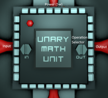
Unary Math Unit[edit]
Connectors[edit]
- Top: Power
- Left: Input
- Right: Output
Screws (options)[edit]
- Left: Input Selector. Click with the Screwdriver to select the input data.
- Right: Operation Selector. Click with Screwdriver to select what operation to run on the Input.
Available Operations[edit]
- Ceil: Rounds the input Up to the closest whole integer.
- Floor: Rounds the input Down to the closest whole integer.
- Abs: Ensures the input is Positive and not Negative (converts -1 to 1, -123.456 to 123.456, etc). Has no effect on positive numbers.
- Log: The natural logarithm of the input. The natural logarithm of x is the power to which e (Euler's number) would have to be raised to equal x.
- Exp: The natural exponential function of the input. e raised to the power of the input.
- Round: Rounds the input to the closest whole integer.
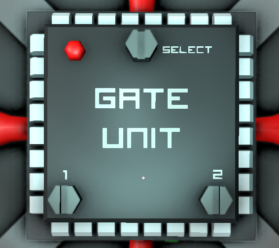
Logic Gate Unit[edit]
Connectors[edit]
- Top: Power
- Left: Input 1
- Right: Input 2
- Bottom: Output
Screws (options)[edit]
- Top: Operation Selector. Click with the Screwdriver to select the logic operation to be performed on the two inputs
- Left: Input Selector. Click with the Screwdriver to select the input data.
- Right: Input Selector. Click with the Screwdriver to select the input data.
Available Operations[edit]
Note: The operations as described below are logical as opposed to bitwise. All non-zero inputs are effectively treated as One or True, therefore an OR operation where input 1 is the value of four and input 2 is the value of one will result in an output of 1 as opposed to 5 as it would be in a bitwise OR.
- OR: Where either inputs are True the output will be True (1), otherwise the output will be False (0)
- AND: Where both inputs are True the output will be True (1), otherwise the output will be False (0)
- XOR: Similar to the OR operation with the exception that if both inputs are True, the output will be False (0)
The following operations simply invert the output of the aforementioned OR, AND and XOR operations.
- NOR: Inverted OR output. If a standard OR operation outputs True (1), this operation will output False (0) and visa-versa.
- NAND: Inverted AND output. If a standard AND operation outputs True (1), this operation will output False (0) and visa-versa.
- XNOR: Inverted XOR output. If a standard XOR operation outputs True (1), this operation will output False (0) and visa-versa.
