Difference between revisions of "Carsten Milkau/D-Latch"
From Unofficial Stationeers Wiki
< User:Carsten Milkau
(→Using Logic Select Unit and Logic Reader) |
m (Carsten Milkau moved page Carsten Milkau/D-Latch to User:Carsten Milkau/D-Latch: This was supposed to be a user page.) |
||
| (2 intermediate revisions by the same user not shown) | |||
| Line 1: | Line 1: | ||
| − | + | A d-latch is a circuit that stores the last value seen at its "data" input while its "enable" input was on. | |
| − | + | == Definition == | |
{| class="wikitable" | {| class="wikitable" | ||
| Line 8: | Line 8: | ||
!colspan="3"|'''inputs'''||'''outputs''' | !colspan="3"|'''inputs'''||'''outputs''' | ||
|- | |- | ||
| − | ! | + | !enable||data||previous output||output |
|- | |- | ||
|0||''x''||''y''||''y'' | |0||''x''||''y''||''y'' | ||
| Line 15: | Line 15: | ||
|} | |} | ||
| − | + | === Connectors === | |
| − | == | + | * enable: if 1, store ''data'', else do nothing. |
| + | * data: input | ||
| + | * output: stored value | ||
| + | |||
| + | == Relation to Multiplexer (Logic Select Unit) == | ||
| − | + | In theory, a single multiplexer ([[Kit_(Logic_Processor)#Logic_Select_Unit|Logic Select Unit]]) can do this (selector input = enable, input 1 = output, input 2 = data, output = output). In practice, this is not possible as the game does not allow it to have its own output as input. However, several constructions using two or more circuits are possible. | |
| − | |||
| − | |||
| − | == | + | == Implementation Using Logic Select Unit and Logic Reader == |
[[File:D-latch.png|thumb|D-latch using select unit and reader]] | [[File:D-latch.png|thumb|D-latch using select unit and reader]] | ||
| Line 30: | Line 32: | ||
<ol> | <ol> | ||
| − | <li>a Logic Select Unit determines whether to store the last output or the "data" input using the " | + | <li>a Logic Select Unit determines whether to store the last output or the "data" input using the "enable" input. i.e. |
| − | <pre> if | + | <pre> if enable |
then store = data | then store = data | ||
else store = output</pre></li> | else store = output</pre></li> | ||
| Line 44: | Line 46: | ||
! Unit name || Unit type || Connector / Setting || Source / Value | ! Unit name || Unit type || Connector / Setting || Source / Value | ||
|- | |- | ||
| − | | select 1 || Logic Select Unit || select || ''' | + | | select 1 || Logic Select Unit || select || '''enable''' (input) |
|- | |- | ||
| || || 0 (input 1) || reader 1 | | || || 0 (input 1) || reader 1 | ||
Latest revision as of 16:07, 18 July 2018
A d-latch is a circuit that stores the last value seen at its "data" input while its "enable" input was on.
Contents
Definition[edit]
| inputs | outputs | ||
|---|---|---|---|
| enable | data | previous output | output |
| 0 | x | y | y |
| 1 | x | y | x |
Connectors[edit]
- enable: if 1, store data, else do nothing.
- data: input
- output: stored value
Relation to Multiplexer (Logic Select Unit)[edit]
In theory, a single multiplexer (Logic Select Unit) can do this (selector input = enable, input 1 = output, input 2 = data, output = output). In practice, this is not possible as the game does not allow it to have its own output as input. However, several constructions using two or more circuits are possible.
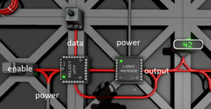
Implementation Using Logic Select Unit and Logic Reader[edit]
This d-latch can store any value. It works in two steps:
- a Logic Select Unit determines whether to store the last output or the "data" input using the "enable" input. i.e.
  if enable
  then store = data
  else store = output
- a Logic Reader mirrors the value to be stored and feeds it back into the select unit so it can circulate (effectively being stored). This would be obsolete if the select unit could read its own output.
output = store
| Unit name | Unit type | Connector / Setting | Source / Value |
|---|---|---|---|
| select 1 | Logic Select Unit | select | enable (input) |
| 0 (input 1) | reader 1 | ||
| 1 (input 2) | data (input) | ||
| reader 1 | Logic Reader | in | select 1 |
| var | setting | ||
| out | output (output) |

