Difference between revisions of "Carticket/ElectricalRevision"
From Unofficial Stationeers Wiki
< User:Carticket
| Line 70: | Line 70: | ||
The breaker panel would be an LV item that takes in current and provides multiple outputs, each with a breaker (maybe adjustable trip points?). The idea would be you place this box somewhere (probably near a transformer), and it provides, say 5 outputs, each rated for 10A. You feed it with a heavy cable, and it gives you safe outputs to run on standard cable. It would effectively function as an LV-LV bridge, separating the networks. This would give you isolation and protection should something get shorted/bridged to HV directly. | The breaker panel would be an LV item that takes in current and provides multiple outputs, each with a breaker (maybe adjustable trip points?). The idea would be you place this box somewhere (probably near a transformer), and it provides, say 5 outputs, each rated for 10A. You feed it with a heavy cable, and it gives you safe outputs to run on standard cable. It would effectively function as an LV-LV bridge, separating the networks. This would give you isolation and protection should something get shorted/bridged to HV directly. | ||
| + | |||
| + | The breaker panel would create one data network across the multiple outputs. | ||
=== Kill-A-Watt Meter === | === Kill-A-Watt Meter === | ||
| Line 77: | Line 79: | ||
=== UPS === | === UPS === | ||
| − | Basically an APC, but functions as an LV-LV bridge like the breaker panel, while also allowing battery backup for small circuits. | + | Basically an APC, but functions as an LV-LV bridge like the breaker panel, while also allowing battery backup for small circuits. I would imagine this would isolate data between the input and output. |
| + | |||
| + | === Data Bridge === | ||
| + | |||
| + | Basically a network over power adapter. I use these in my house. The data network is added as a signal on top of the actual voltage in the power lines. It takes data + voltage on one side, and gives data only on the other. In game, it would serve as a data network pass-through without connecting the two networks for power purposes. It could be used to bridge data from HV to LV networks, or maintain a separate data network from all power. | ||
| + | |||
| + | == Data Network == | ||
| + | |||
| + | The data network would extend as far as the power network goes, with some devices also functioning as data bridges. Electrical bridges (APC, Transformer, UPS, Breaker Box) would have distinct input and output networks (though the breaker box, with multiple outputs, would have one single output network shared on all outputs). The data bridge mentioned earlier would allow for user-defined data connections across networks without having a power connection between the networks. | ||
| + | |||
| + | With an example of automated solar, this would allow the logic circuit to run in an LV network and a data bridge connected to the HV network would allow it to write tilt percentages to the solar array. | ||
== Examples == | == Examples == | ||
Latest revision as of 16:27, 26 December 2017
Contents
Summary[edit]
This is a proposal for a revision to the electrical system, to better model how real life works. I believe the changes to functionality and calculations are relatively minor, with little impact to how parts are used. The proposal, in short, is to model the system not with Watts, but with voltage and amperage (current). To keep realism, but maintain simplicity, the system will either model everything as AC, or as DC (it is not particularly important which is used), and either high voltage or low voltage.
Basic System[edit]
The system would divide devices into four categories based on two properties: high vs. low voltage, and current source vs. sink.
| High Voltage | Low Voltage | |
|---|---|---|
| Current Source |
|
|
| Current Sink |
|
|
For current sources, they would have a specified current output at either HV or LV. For current sinks, they would have a specified input current. These are not constant, just as watts generator or watts consumed is not currently constant.
For a given voltage, current and power are proportional. This proportion changes between the two voltage levels, though.
Bridge High Voltage to Low Voltage[edit]
In order to bridge HV and LV networks, you need to drop the voltage. I don't think there is a need to have bidirectionality here (i.e. send power from LV to HV networks). We will treat everything as a step-down transformer (if AC. Power Supply if DC). There are two devices that would currently function as HV to LV bridges:
- Transformer
- APC
Both of these would have an input side that takes in power from a high voltage network, and outputs the same power on the low voltage output. If I propose a 10:1 factor of HV to LV, then if you have 10A of high voltage source capacity connected to the input of the transformer, then that gives you 100A of low voltage source capacity on the output. The transformer would be modeled exactly this way. The APC would also model a low voltage battery source/sink in addition to a transformer.
When Things Should Blow Up[edit]
Everything would be rated for a current capacity. Standard cable may be rated for 15-20 A (comparable to in-home 120 V AC wiring in real life) [perhaps simplify to 10A for easy calculation]. Heavy cable would be rated for approximately 10 times (or whatever the HV:LV ratio is) the amount that standard is rated for (similar to the input to your in-home breaker panel). The transformer and APC would be rated based on either input or output current, and the HV:LV ratio would determine the other rating.
Exceeding the rated current capacity for a cable or other pass-through device could cause an immediate destruction, or it could be more complex. A complicated model for running outside the rating would include heat generation starting at the limit, which builds over time. The further beyond the rating you go, the faster the heat is generated. Then devices would basically have a meltdown point, passing which, they explode or are destroyed in some way.
Connecting an LV device to an HV network should cause immediate damage (maybe it can be repaired with some sort of repair component and the screwdriver?). Connecting an HV network to an LV network would blow out the LV devices on the network, and if there are LV sources on the network, it would cause a short, draining the maximum current possible from the HV network, likely blowing up some wires, too.
Battery Model[edit]
Batteries would be rated with a maximum input charge current, and a maximum output discharge current. Their charge capacity would be measured in a unit analogous to Amp*Hours, but may need to be scaled to something reasonable (Amp*Minutes, etc, depending on how batteries end up balanced in this system). The stationary battery, running on HV networks, may have something like a 10 AH capacity, which may match the large battery cell capacity, but given that it is at a voltage 10x higher, it actually supports 10x the runtime for LV devices.
What Happens When There's Not Enough Power?[edit]
Brownouts. How do we model them? I'm not really sure yet. I would propose that if a total current sink cannot be satisfied, devices brown out. Output devices would shut down temporarily (it would be mean to make the devices lose progress like they do now, so I'd suggest they retain progress on crafting). Devices could be randomly selected every second to shutdown for 10 seconds until the current sink can be satisfied. If demand is still not met, then a second later another device shuts down at random. After the 10 seconds, the device would attempt to power back up. At this point, it could be implemented as the device remaining off if demand can't be met, or it turns back on and another one is randomly shut off.
Transformers would never be selected to be shut off, as they are a simple bridge rather than sinking the current themselves. Batteries would be low priority for charging (using up to as much current capacity as it is rated for until the battery is full), and so they would have stopped charging (and if a stationary battery, APC, or new battery device [UPS], would begin discharging).
What Happens When There's Too Much Power[edit]
Assume that every source has the capability to sink excess power to ground. Maybe heat up the area to simulate conversion to heat? Not really sure a lot of detail needs to be done here.
New Objects[edit]
There would be a few new objects to use as a part of the system, optionally.
Breaker Panel[edit]
The breaker panel would be an LV item that takes in current and provides multiple outputs, each with a breaker (maybe adjustable trip points?). The idea would be you place this box somewhere (probably near a transformer), and it provides, say 5 outputs, each rated for 10A. You feed it with a heavy cable, and it gives you safe outputs to run on standard cable. It would effectively function as an LV-LV bridge, separating the networks. This would give you isolation and protection should something get shorted/bridged to HV directly.
The breaker panel would create one data network across the multiple outputs.
Kill-A-Watt Meter[edit]
Functions like the real-life device, but not using a trademarked name. Place in line with a wire to monitor voltage (HV vs LV), current flow, and maybe come up with some other stats? Really, it would just be the current monitoring that would be useful.
UPS[edit]
Basically an APC, but functions as an LV-LV bridge like the breaker panel, while also allowing battery backup for small circuits. I would imagine this would isolate data between the input and output.
Data Bridge[edit]
Basically a network over power adapter. I use these in my house. The data network is added as a signal on top of the actual voltage in the power lines. It takes data + voltage on one side, and gives data only on the other. In game, it would serve as a data network pass-through without connecting the two networks for power purposes. It could be used to bridge data from HV to LV networks, or maintain a separate data network from all power.
Data Network[edit]
The data network would extend as far as the power network goes, with some devices also functioning as data bridges. Electrical bridges (APC, Transformer, UPS, Breaker Box) would have distinct input and output networks (though the breaker box, with multiple outputs, would have one single output network shared on all outputs). The data bridge mentioned earlier would allow for user-defined data connections across networks without having a power connection between the networks.
With an example of automated solar, this would allow the logic circuit to run in an LV network and a data bridge connected to the HV network would allow it to write tilt percentages to the solar array.
Examples[edit]
Survival Start[edit]
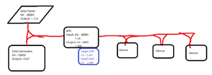
We already have the pieces used here. Nothing really changes, and it shouldn't. Actual numbers here are for demonstration purposes only and may not actually reflect a balanced system.
With Stationary Battery and Transformer[edit]
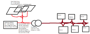
All the pieces are already here for this, too. Lets you use standard cable on the HV side, but heavy cable is needed on the LV side if devices could sink more than 10A total.
The Ultimate Setup[edit]
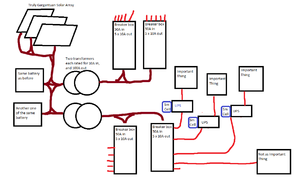
This setup uses multiple batteries to store lots of potential power and a huge solar array. The details for generation are not so important. What this shows is creating two segmented LV networks using two transformers. Each transformer feeds two breaker boxes (each capable of supplying 5 10A LV circuits). It also shows one breaker box being used for important things and so the user has decided to put a UPS on those things with a small cell. This would help those devices stay up through a brownout, for example at night when the solar is not generating, if the stationary battery source capacity were exceeded.


