Kit (Logic I/O)
From Unofficial Stationeers Wiki
 | |
| Operation | |
|---|---|
| Power Usage | 10W |
| Construction | |
| Placed with | Kit (Logic I/O) |
| Placed on | Small Grid, On Frames |
| Stage 1 | |
| Deconstruction | |
| Deconstructed with | Hand Drill |
 | |
| Operation | |
|---|---|
| Power Usage | 10W |
| Construction | |
| Placed with | Kit (Logic I/O) |
| Placed on | Small Grid, On Frames |
| Stage 1 | |
| Deconstruction | |
| Deconstructed with | Hand Drill |
 | |
| Operation | |
|---|---|
| Power Usage | 10W |
| Construction | |
| Placed with | Kit (Logic I/O) |
| Placed on | Small Grid, On Frames |
| Stage 1 | |
| Deconstruction | |
| Deconstructed with | Hand Drill |
 | |
| Operation | |
|---|---|
| Power Usage | 10W |
| Construction | |
| Placed with | Kit (Logic I/O) |
| Placed on | Small Grid, On Frames |
| Stage 1 | |
| Deconstruction | |
| Deconstructed with | Hand Drill |
 | |
| Operation | |
|---|---|
| Power Usage | 10W |
| Construction | |
| Placed with | Kit (Logic I/O) |
| Placed on | Small Grid, On Frames |
| Stage 1 | |
| Deconstruction | |
| Deconstructed with | Hand Drill |
 | |
| Operation | |
|---|---|
| Power Usage | 10W |
| Construction | |
| Placed with | Kit (Logic I/O) |
| Placed on | Small Grid, On Frames |
| Stage 1 | |
| Deconstruction | |
| Deconstructed with | Hand Drill |
The Logic Input/Output Unit is used to Read (input) data from any machine with a data port connected through the data network, or Write (output) data to any machine with a data port connected to trough the data network. The Input, Output and Power networks can be completely separated.
Contents
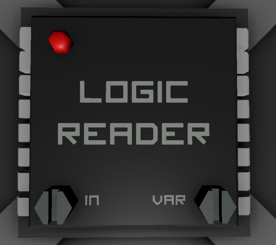
Logic Reader
Connectors
- Left: Data Input
- Top: Power Input (10w)
- Right: Data Output
Screws
- Left: Input Selector. Click with Screwdriver to select from which machine to read from. Only machines with a data port connected though the cables connected to the left port can be read from.
- Right: Variable Selector: Click to select what Variable to output into the network on the right. Different machines will have different available variables to read from.
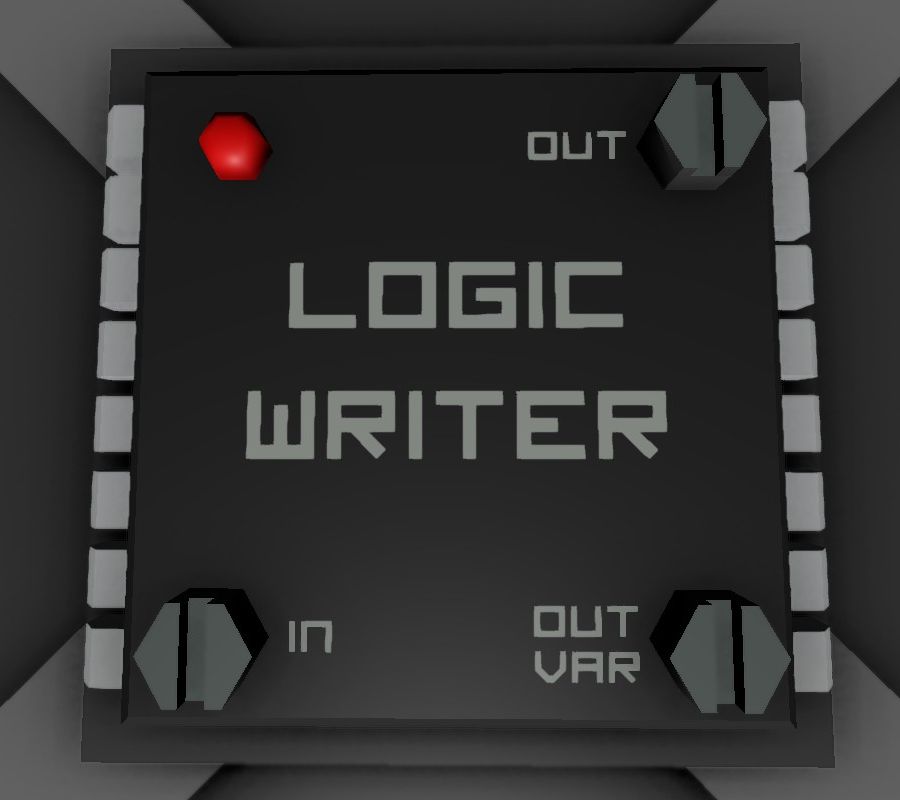
Logic Writer
Connectors
- Left: Data Input
- Top: Power Input (10w)
- Right: Data Output
Screws
- Bottom Left: Variable Input Selector: Click with Screwdriver to select the value to input. This can be directly from a machine, another logic circuit, a computer, etc.
- Top Right: Machine Write Selector. Click to select what machine to write to. Only machines with a data port connected though the cables connected to the right port can be written to.
- Bottom Right: Variable Selector: Click to select what variable to write to the machine. The value written will be what is captured by the Variable Input Selector.
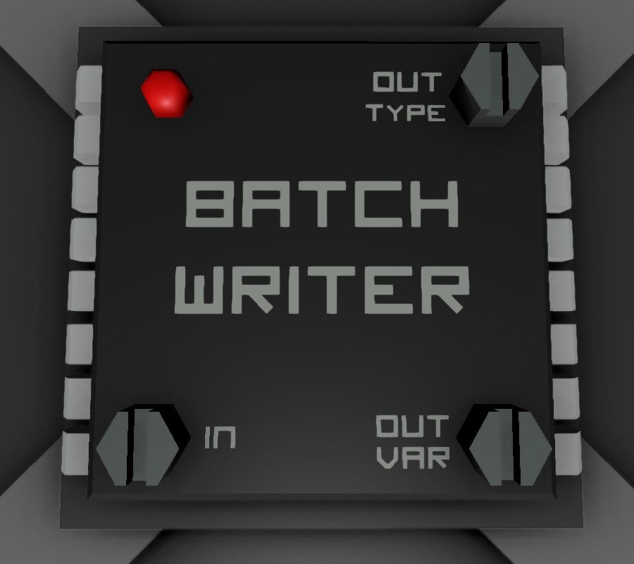
Batch Writer
The Batch Writer writes to all conected devices of a device type. For example: One can control all digital valves connected in its network with a single Batch Writer.
Connectors
- Left: Data Input
- Top: Power Input (10w)
- Right: Data Output
Screws
- Bottom Left: Variable Input Selector: Click with Screwdriver to select the value to input. This can be directly from a machine, another logic circuit, a computer, etc.
- Top Right: Machine Type Selector. Click to select what machine type to write to. All machines of that type will recieve the exact same data. For example selecting Solar Panel will write to all solar panels on the network.
- Bottom Right: Variable Selector: Click to select what variable to write to the machines. The value written will be what is captured by the Variable Input Selector.
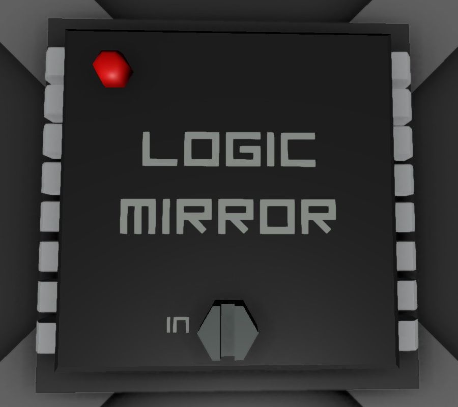
Logic Mirror
The Logic Mirror is mirroring all data from it's target device. It's purpose is to easily get access to a device in another network. The Logic Mirror itself is visible in the logic network as a mirror of the target device. Writing and reading is possible as if the target device itself is present in the logic network. If the Logic Mirror is not powered, it will not return any data.
Example
You have a gas sensor in network-1 and want to read "RatioNitrogen", "RatioPollutant", "RatioVolatiles" and "RatioWater" into network-2.
- Without the Logic Mirror: 4 Logic Readers are needed. If you later also want to access "Pressure" and "Temperature", two more Logic Readers are needed. Writing something to a device would require additional Logic Writers.
- With the Logic Mirror: Only one single Logic Mirror is needed. If you later want to access "Pressure" and "Temperature" you can do it without any new logic chip. Writing something to a device is also always possible.
Connectors
- Left: Mirrored Device
- Top: Power Input (10w)
- Right: Data Input/Output
Screws
- Centre: Variable Mirroring Selector: Click with Screwdriver to select the device to mirror. This can be any machine, logic circuit, computer, etc.
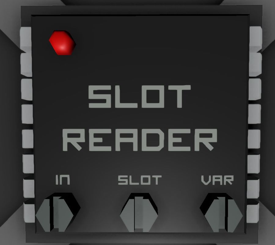
Slot Reader
Connectors
- Left: Data Input
- Top: Power Input (10w)
- Right: Data Output
Screws
- Left: Variable Input Selector: Click with Screwdriver to select the value to input. This can be from any device that has inventory slots, etc.
- Centre: Slot Selector: Click to Select which slot to read from.
- Right: Variable Selector: Click to select what variable to output into the network on the right.
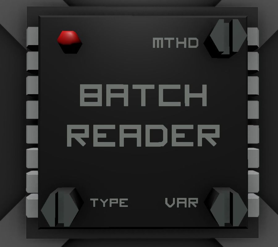
Batch Reader
The Batch Reader is sort of the opposite of a Batch Writer - It can read from all connected devices of a device type.
For example: One can read from all Kit (Battery) and then average or sum the capacities, and output the value to another device.
Connectors
- Left: Data Input
- Top: Power Input (10w)
- Right: Data Output
Screws
- Bottom Left: Variable Input Selector: Click with Screwdriver to select from which machine type to read from.
- Top Right: Method Selector. Click to select by which method to pull data.
- Bottom Right: Variable Selector: Click to select what variable to output into the network on the right.
