Difference between revisions of "PowerTransmitter"
From Unofficial Stationeers Wiki
m |
m |
||
| Line 89: | Line 89: | ||
#..and the Logic Transmitter can be unpowered | #..and the Logic Transmitter can be unpowered | ||
| − | #Transmitter | + | #Power Transmitter data-port must point NORTH |
| + | #Power Reciever data-port must point NORTH | ||
#transmitter = Microwave Power Transmitter | #transmitter = Microwave Power Transmitter | ||
Revision as of 17:05, 18 August 2022
| Properties | |
|---|---|
| Stacks | Yes (10) |
| Recipe | |
| Created With | Electronics Printer |
| Cost | 5 Gold, 7 Copper, 3 Steel |
| Operation | |
|---|---|
| Power Usage | 10W |
| Construction | |
| Placed with | Kit (PowerTransmitter) |
| Placed on | Large Grid |
| Stage 1 | |
| Deconstruction | |
| Deconstructed with | Hand Drill |
| Item received | 3x Electronic Parts |
| Stage 2 | |
| Deconstruction | |
| Deconstructed with | Hand Drill |
| Item received | 2x Iron Sheets |
| Stage 3 | |
| Deconstruction | |
| Deconstructed with | Hand Drill |
| Item received | Kit (PowerTransmitter) |
| Operation | |
|---|---|
| Power Usage | 10W |
| Construction | |
| Placed with | Kit (PowerTransmitter) |
| Placed on | Large Grid |
| Stage 1 | |
| Deconstruction | |
| Deconstructed with | Hand Drill |
| Item received | 1x Electronic Parts |
| Stage 2 | |
| Deconstruction | |
| Deconstructed with | Hand Drill |
| Item received | 2x Iron Sheets |
| Stage 3 | |
| Deconstruction | |
| Deconstructed with | Hand Drill |
| Item received | Kit (PowerTransmitter) |
Contents
Description
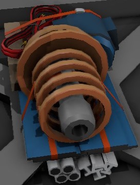
The Norsec Wireless Power Transmitter is an uni-directional, A-to B, far field microwave electical transmission system. The rotatable base transmitter delivers a narrow, non-lethal Microwave beam to a dedicated base receiver.
The transmitter must be aligned to the base station in order to transmit any power. The brightness of the transmitter's collimator arc provides an indication of transmission intensity. Note that there is an attrition over longer ranges, so the unit requrires more power over greater distances to deliver the same output.
General behaviour
- 5kW is the maximum PowerPotential that can be transmitted, this amount is reduced by distance.
- Unaffected by storms.
- Using two emitters on the same reciever doesn't appear to work
- A Logic Transmitter can mirror recievers, but not emitters.
- The coordinates of these devices will change slightly when the head moves.
- Both structures and terrain will block the beam. Once a beam is formed it will no longer be blocked by building things between them.
- When these devices are built their placement rotation is important. The easiest way is to point the data-port to the north (0° on the space suit compass), otherwise a horizontal correction angle must be added or subtracted when doing the math.
- When the device head is being rotated horizontally it is rotating in the opposite of the expected direction, this must be compensated for when doing the math.
Range
Power transfer with 4000 W PowerPotential
98m = 3630 W (-0.37kW)
198m = 2863 W (-1.14kW)
300m = 1409 W (-2.59kW)
400m = 0 W
Power transfer with 5000 W PowerPotential
98m = 4630 W (-0.37kW)
198m = 3863 W (-1.14kW)
300m = 2409 W (-2.59kW)
400m = 651 W (-4.35kW)
Alignment formulas
All dataports points north, the delta values are calculated from: "reciever coordinate" - "emitter coordinate"
Horizontal for "emitter" = atan2( delta-x / delta-z ) * 180 / pi
Vertical for "emitter" = 90 + atan( delta-y / sqrt( (delta-z)^2 + (delta-x)^2 ) ) * 180 / pi
Horizontal for "reciever" = 180 + Horizontal for "emitter"
Vertical for "reciever" = 180 - Vertical for "emitter"
Comments:
When the data-port points north, +0° is added to the Horizontal rotation.
When the Vertical rotation is 90° the device head points towards the horizon, 90° must be added because when delta-y is 0 (no height difference) then atan() will be 0
Both atan2() and atan() uses radians for the angle, radians are converted to degrees by multiplying with 180 / pi
atan2(x/z) should be z/x in a normal situation, but it has been inverted to compensate for the devices inverted rotation direction
atan(y/x) uses Pythagoras theorem to set x as the horizontal-plane distance between emitter and reciever
IC script
##POWER TRANSMITTER ALIGNMENT##
#When the alignment is complete, this IC housing..
#..and the Logic Transmitter can be unpowered

#Power Transmitter data-port must point NORTH
#Power Reciever data-port must point NORTH

#transmitter = Microwave Power Transmitter
alias transmitter d0
#reciever = Logic Transmitter linked to the..
#..Microwave Power Reciever
alias reciever d1

alias deltaX r13
alias deltaZ r14
alias deltaY r15
define pi 3.1415

main:
yield
#calculate delta values
l r0 reciever PositionX
l r1 transmitter PositionX
sub deltaX r0 r1
l r0 reciever PositionZ
l r1 transmitter PositionZ
sub deltaZ r0 r1
l r0 reciever PositionY
l r1 transmitter PositionY
sub deltaY r0 r1

#Horizontal for "transmitter"
#atan2(deltaX/deltaZ)*180/pi
atan2 r0 deltaX deltaZ
mul r0 r0 180
div r0 r0 pi
s transmitter Horizontal r0

#Horizontal for "reciever"
#180 + Horizontal for "emitter"
add r0 180 r0
s reciever Horizontal r0

#Vertical for "transmitter"
#atan(deltaY/sqrt(deltaX^2+deltaZ^2))*180/pi+90
mul r0 deltaX deltaX
mul r1 deltaZ deltaZ
add r0 r0 r1
sqrt r0 r0
div r0 deltaY r0
atan r0 r0
mul r0 r0 180
div r0 r0 pi
add r0 r0 90
s transmitter Vertical r0

#Vertical for "reciever"
#180 - Vertical for "transmitter"
sub r0 180 r0
s reciever Vertical r0
j main


